The Control tab controls the Multitone measurement by determining
Besides, it configures the measurement diagram by adding or removing the Grid. All parameters can be set independently for the two AF channels 1 and 2.
 |
|
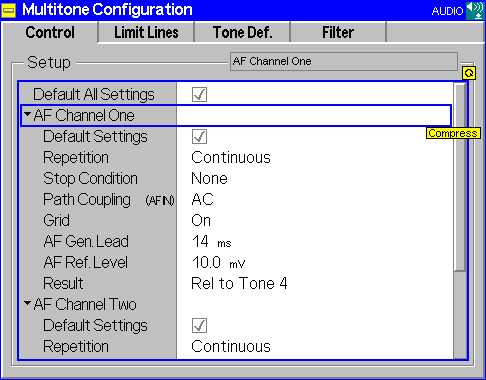
Multitone Configuration - Control
| Default Settings | The Default switch assigns default values to all settings in the Control tab (the default values are quoted in the command description in chapter 6 of this manual). Two additional default switches reset all AF Channel 1 or all AF Channel 2 settings, respectively. |
|
Remote Control | |
| Repetition | The Repetition field determines the repetition mode, see explanations given in section Measurement Configurations (Power Configuration) for the Power measurement. In Audio, one statistics cycle is terminated when the system has settled and a valid result is available. |
|
Remote control | |
| Stop Condition | Stop Condition table defines a stop condition for the measurement: |
| None | Continue measurement even if tolerance is exceeded. |
| On Limit Failure | Stop measurement if tolerance is exceeded. |
|
Remote control | |
| AF Path Coupling |
AF Path Coupling sets the input path for measurement of the AC or AC and DC component of the AF signal: |
| AC | DC component of the measured AF signal (including a possible DC offset of the input amplifier) blocked. This ensures accurate measurement of the AC component. The DC component, however, can not be measured. |
| DC | Measurement of the complete AF input signal (DC plus AC components). |
| Note: The AF path coupling has an impact on the allowed filter settings; see section Input Path Configuration (Multitone Configuration - Filter). | |
|
Remote control | |
| AF Generator Lead | AF Generator Lead defines a settling time for the measurement to be applied after a change of the generator settings. A small value accelerates the measurement but may impair its accuracy. |
|
Remote control | |
| AF Ref. Level | AF Ref. Level defines an audio reference level. The reference level is entered as an RMS voltage (in mV) and defines the 0 dB line of the test diagram provided that Relative to Ref. Lev. is selected as Result Mode (see below). |
|
Remote control | |
| Result | The Result function defines the reference value for all measurement results. This corresponds to the 0 dB reference line in the diagram. |
| Relative to Ref. Lev. | All results are referenced to the AF Ref. Level; see above |
| Relative to Tone 1
... |
All results are referenced to the measurement result at tone 1 (if available) |
| Relative to Tone 20 | All results are referenced to the measurement result at tone 20 (if available) |
| The measurement is taken at up to 20 audio frequencies (tone 1 to 20) which can be defined and switched on or off in the Tone Def. tab of the configuration menu (see Test Tones (Multitone Configuration - Tone Def.)). | |
|
Remote control |