|
|
 |
Stepping the Duty Cycle of a Pulse Source
There are a couple of ways to step the duty cycle of a pulse source. Since up to ten parameters may be stepped in the Stepping dialog box, you can set the stepping for each timing parameter in the pulse model statement separately. However, the timing parameters in the pulse source model statement must meet the following condition:
P1 <= P2 <= P3 <= P4 <= P5
Therefore, any timing parameter that is stepped needs to track the other timing parameters to insure that this condition is not violated. This can lead to a good deal of editing in the Stepping dialog box. An easier method is to use a symbolic parameter and to step that parameter.
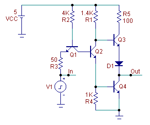
The circuit below uses a pulse source as an input that feeds into a TTL inverter. The pulse source has been defined with the following model statement:
.Model VDuty Pul (Vzero=0 Vone=3.5 P1=1n P2=2n P3=Fall P4=Fall+1n P5=100n )
where Fall is a symbolic parameter that controls the Vone to Vzero transition of the pulse source. In this case, the pulse source will start to fall from its Vone value at Fall seconds. It will reach its Vzero value at Fall+1n seconds with the fall time always being equal to 1ns. The P1, P2, and P5 values are fixed for this circuit although the symbolic parameter can be applied to them also if necessary. The Fall parameter is then defined through a .Define statement that has been placed in the text area such as:
.Define Fall 40n
|

|
Instead of having to step both P3 and P4 in the Stepping dialog box, only the Fall parameter needs to be stepped. For this analysis, the Fall parameter will be stepped from 30ns to 70ns in linear steps of 10ns. This is done by selecting Symbolic in the Parameter Type section of the Stepping dialog box and setting the text fields as below:
|
| Step What |
Fall |
| From |
30ns |
| To |
70ns |
| Step Value |
10ns |
| |
The transient analysis results of this circuit appear below. The output of the pulse source appears in the top plot of the analysis. As can be seen in the analysis results, the duty cycle of the pulse steps from 30% to 70% as expected. The waveform at the bottom is the voltage output of the inverter.
|
|
This is a powerful stepping technique. It is not confined to a single model or component type. The same symbolic parameter may be used in as many components, expressions, or model parameters as needed. For model statements, any type of static equation may be used within the statement. Dynamic variables, such as V(1) or I(R1), are not allowed within a model statement.
|
|
|
|
|


