|
|
 |
Animate Mode
Animate mode is an analysis mode where animation objects can change their display or respond to user clicks during a simulation. Animation mode is primarily designed to operate in transient analysis with digital components. However, it is available in any analysis with any type of circuit. In AC analysis, it will only show the operating point voltages and digital states during the entire simulation. Any animation components will be fixed at their operating point state. In DC analysis, the node voltages, digital states, and animation component displays will change along with the simulated results. The strength of this mode lies in its use during transient analysis. In this mode, a single analysis time step is taken and the node voltages, digital states, and animated devices will update on the schematic. The purpose of the animate mode is to slow the simulation down to show individual node voltage or state changes and to provide diagnostic components to view simulation results on the schematic. There are three animation components: a digital switch, an LED, and a seven segment display. The description of these are as follows:
Digital Switch - This switch is designed to produce either a digital zero or one state. It has a single output at which the specified digital state will appear. During a simulation, the switch may be clicked on to toggle it between its zero and one state. The appearance of the switch's arm will change to indicate which state the switch is currently connected to.
|

|
LED - This component is designed to represent the display of a light emitting diode. It has a single input pin. Depending on the digital state or the analog voltage at the input pin, the LED will display a different color on the schematic. The colors the LED uses are defined in the Preferences dialog box under the Analysis/Performance Defaults section. In this section, there is a list of digital states that have a corresponding defined color.
|
Seven Segment Display - This component is designed to represent the display of a seven segment display. It has an input pin for each segment of the display. All of the inputs are active high. It is intended to work with basic seven segment decoders/drivers although any input will control the display of the corresponding segment.
|

|
These three components do not model the electrical characteristics of the parts they represent. They are only available for display purposes. The digital switch is the only one of the three that can effect a simulation. Each of these components must have an I/O model specified for them in order to work with analog components. This I/O model translates any analog voltage into its equivalent digital state.
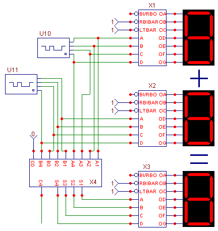
The circuit below (anim3.cir - MC5 V2 only, Save As to your disk and then load in MC5) uses the seven segment components to display the outputs of three seven segment decoders. The circuit consists of two 4-bit digital stimuli, three 7448 BCD to seven segment decoders, one 7483A 4-bit binary full adder, seven fixed digital components, and three seven segment displays. The digital stimuli each have their FORMAT attribute defined as 4, and the COMMAND attribute has been defined as Ina for one and Inb for the other. Ina and Inb are then defined in the text area as:
.define Ina
+0ns 0
+100ns 3
+200ns 1
+300ns 0
+400ns 7
+500ns 3
+600ns 5
+700ns 2
+800ns 6
+900ns 3
.define Inb
+0ns 7
+100ns 6
+200ns 1
+300ns 4
+400ns 1
+500ns 2
+600ns 1
+700ns 0
+800ns 2
+900ns 0
These .define statements set the hexadecimal value of the digital stimuli outputs at the specified times. The fixed digital components are used to fix the RBIBAR and LTBAR pins on the 7448 decoders to a high state and to fix the input carry pin of the 7483A to a low state. The two stimuli are then input to the 7483A adder. The output of the adder is connected to the input of a 7448 decoder. Each of the stimuli are also connected to the input of a 7448 decoder. All three decoders have a seven segment display attached to the output to display the results. The seven segments displays will display the value of the digital stimuli and the resultant sum produced from the adder.
|

|
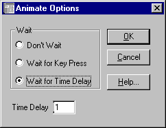
Only a transient analysis can be run on this circuit since there are no analog devices. The simulation time has been set to 1u. Clicking on the Scope menu and then Animate Options invokes the dialog box below. There are three options available for the analysis: Don't Wait, Wait for Key Press, Wait for Time Delay. Don't Wait runs the analysis as it normally would. Wait for Key Press forces the user to press a key to calculate the next time point. Wait for Time Delay means that the delay specified in the Time Delay text field must elapse before the next time point is calculated. For this circuit, the time delay method has been chosen with a delay of 1s.
|

|
For animate mode, a split screen should be used to be able to view both the waveform plot and the schematic at the same time. The schematic can be moved within the window by dragging with the right mouse button. Two of the display states are shown below. The first figure occurs between 100ns and 200ns when the value of Ina is 3 and the value of Inb is 6, and the third seven segment display shows the resulting sum of 9. The second figure occurs between 600ns and 700ns when the value of Ina is 5 and the value of Inb is 1, and the third seven segment display shows the resulting sum of 6.
The waveforms in the plot also show the value of Ina (nodes 21-18), Inb (nodes 28-25), and the resulting output (nodes 35-32) of the adder. As can be easily seen in the figures, it is much easier to view the basic output through the animation components than through the actual waveforms.
|
|
|
|
|


