|
|
 |
Wideband Transformer Macro
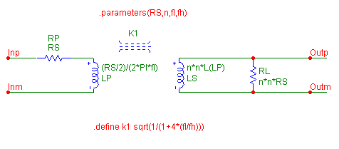
A wideband transformer is a transformer that is designed to pass a frequency band of several decades. These transformers are usually used to handle complex waveforms rather than simple sinusoidal waveforms or for impedance matching. The macro model for the wideband transformer appears in the figure below. This model was derived from the article "Spice model simulates broadband transformer" by Michael Steffes which appears in the February 15, 1996 Design Ideas Supplement for EDN.
The macro is a simple circuit consisting of two inductors, two resistors, and a coupling K device. However, data sheets for wideband transformers typically specify four parameters: the impedance ratio, the two -3dB frequencies of the bandpass response, and the primary impedance that the frequencies were measured at. The macro imports these four parameters. RS is the primary impedance, n is the square root of the impedance ratio, fl is the low -3dB frequency, and fh is the high -3dB frequency. Therefore, the two inductances, the coupling coefficient, and the secondary impedance will all need to be calculated from these parameters with the following equations:
LP = (RS/2)/(2*PI*fl)
LS = n*n*LP
k = (1/sqrt((1+4*(fl/fh))))
RL = n*n*RS
The LP, LS, and RL VALUE attributes all have the appropriate equation above defined directly into the attribute. The K1 COUPLING attribute is defined as K1, and then a .define statement is used to input the equation. Either method will produce the same results. As this is a macro circuit, the desired input and output pins have all been labelled with text. In this case, the nodes have been named as Inp, Inm, Outp, and Outm.
|

|
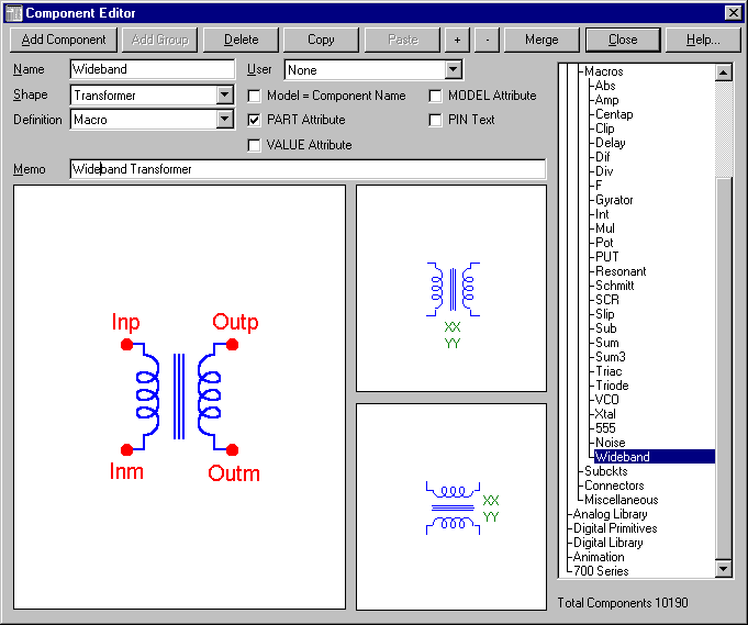
The Component Editor settings for the wideband transformer macro appear below. The name of the macro is the same as the macro circuit that was created, Wideband. It has been given the transformer shape and macro definition. Four pins have been added to the shape. Note that the pin names match exactly with the node names that were defined in the macro circuit.
|

|
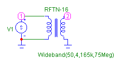
The test circuit for the macro appears below. This is a simple test circuit designed to analyze the frequency characteristics of a RFTN-16 transformer. The V1 source has its VALUE attribute defined as AC 1 for a 1V AC small signal source. The Wideband macro has its VALUE attribute defined as:
Wideband(50,4,165k,75Meg)
This describes a transformer with a primary impedance of 50 ohms, an impedance ratio of 16 (n2), a low -3dB frequency at 165KHz, and a high -3dB frequency at 75MHz.
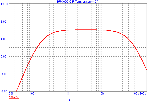
The AC analysis results appear below the schematic and display the bandpass response of the transformer. The circuit has been swept from 20KHz to 200MHz, and the output voltage of the macro has been plotted in dB. The two -3dB frequencies have been denoted with cursors, and as can be seen, they are at the points in which the gain is -3dB down from its 6dB peak. The 6dB peak is correct as the midband gain is calculated as:
Vo/Vi = n*(RL/(RL+n*n*RS)) = n/2
Vo/Vi = 2 = 6dB
This macro is only applicable when the ratio of fh/fl is greater than 100.
|

|

|
|
|
|
|


