|
|
 |
Introducing Micro-Cap V Version 2.0
The latest version of Micro-Cap, Micro-Cap V Version 2.0, will be available for shipping by June 1.
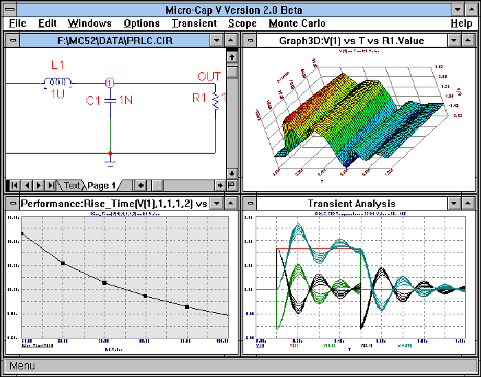
This version has many improvements and added features in both its capabilities and its interface. A preview of some of the features follows. Upon request, all purchases of Version 1.0 between 4/1/97 and the introduction date of 6/1/97 will receive a free upgrade.
|

|
Performance Plotting
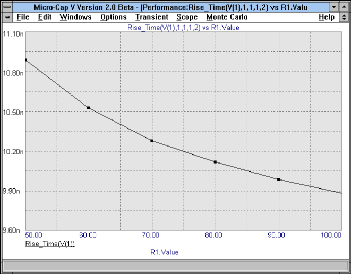
Performance plotting is a method for displaying data from an analysis that contains multiple runs. MC5 provides a group of functions for measuring performance related curve characteristics. These functions let you measure performance related values such as rise time, fall time, pulse width, frequency, period, and many others. These functions also exist for use in cursor mode, in order to quickly place the cursors across a desired measurement.
Common usage of the performance plotting feature would occur in an analysis that contains temperature stepping or component stepping. For example, the sample circuit PRLC.CIR has its resistor stepped from 50 ohms to 100 ohms in increments of 10 ohms. Performance plotting lets you plot a graph of a characteristic of these curves versus the stepped resistance. The figure below displays the performance plot of the rise time of the circuit measured between .5 volts and 4.5 volts versus the resistance value.
|

|
3D Plotting
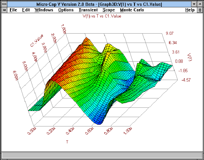
Another method for displaying information from a multiple run analysis in Version 2.0 is through 3D plotting. 3D plotting lets you display a plot of three of the variables at the same time. Instead of a single measurement, such as in the performance plot, you can view all of the data in relation to one another. This display method would also be most commonly used in the case of stepping components or stepping temperature.
The appearance of the plot may be altered by the user. The 3D plot may be rotated by mouse or by keyboard. The X, Y, and Z views may all be profiled. The color of the plot is controlled by the user, and it may vary from a spectrum of colors, to a single color, to a wire mesh representation of the plot. Instead of the standard 3D plot, a contour plot may also be produced with the same information.
An example of 3D plotting appears in the figure below. Once again, the circuit PRLC was used. This time the capacitor was stepped from a value of 1n to 6n in increments of 1n. The 3D graph displays a plot of capacitance versus time versus the voltage at node 1.
|

|
Stepping Improvements
There have been major additions to the stepping routines in Version 2.0 that greatly enhance their capabilities. First of all, symbolic stepping has been added. Any variable that is defined through a .define or a .param statement may now be stepped. This gives you the power to step constants in an equation, or to step multiple parameters that reference the same value. For example, the P2 and P3 parameters of a pulse source may be defined with the same symbolic name. Stepping this name would let you step the peak of a triangle source.
A second feature added was to include a List method along with the standard Log and Linear methods. The List method lets you place a list of values into the Stepping dialog box that the parameter will be stepped through. Any set of values may be stepped now instead of having to have it be linearly or logarithmically related.
The final feature added was to include the capability of stepping multiple parameters. Version 2.0 may step up to 10 parameters in the same analysis. These parameters may be stepped in either a nested or simultaneous mode. Any combination of component parameters, model parameters, or symbolic parameters may be stepped together.
Larger Model Library
The device model library has now been expanded to over 10000 parts. The digital library now includes over 100 ECL parts from National and Motorola, and the number of parts in the existing families have all been increased. The analog portion of the library has been expanded with European and Japanese diodes and transistors along with current regulators from Motorola. New vendor supplied subcircuits include sensors from Motorola, varistors from Siemens, MosFETs from Harris, and IGBTs from International Rectifier.
New Device Models
New device models that have been added in to the analog primitives are z-transform sources and a sample and hold element. We have also added in the BSIM MosFET models. The BSIM levels added are BSIM1, BSIM2, and BSIM3 Version 3.
Probe Improvements
The Probe method of analysis has undergone some major changes. The basic operation of clicking on the schematic to call up a waveform is the exact same. However, the user now has much more control of the placement and visual attributes of the waveform. There is now a Graph option which performs the same function as the P column in the Transient Analysis Limits dialog box in that it lets you place probed waveforms on up to nine different graph groups. A big advancement in Probe is that it now lets you enter expressions to be plotted. It can handle any of the expressions that the standard analysis uses.
Improved Waveform Controls
Version 2.0 offers a lot more capabilities in manipulating a waveform after it has been plotted. These changes apply to both standard analysis and Probe analysis. It is now possible to have multiple Y scales for a single graph, and the ranges on these Y scales and on the X scale may be manually changed after the waveform is plotted. You may transfer waveforms from one plot group to another, or simply have the waveform not displayed in case it interferes with another waveform. Finally, it is possible to change the thickness of the waveform in order to improve its visibility on printouts or on the monitor.
Animation
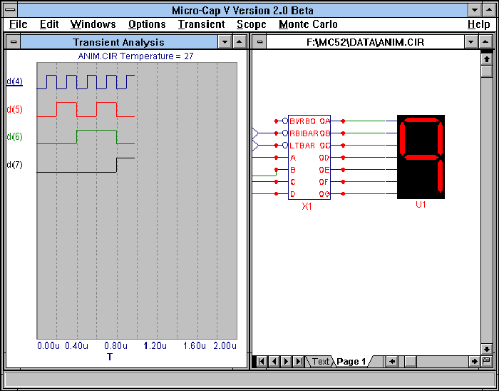
There have been a few new parts added into Version 2.0 to help with digital analysis. These parts act in conjunction with our new animate options. The animate options tell the simulator to produce one data point each time a key is pressed or when a specified length of time has elapsed. The new parts added are a seven-segment display, a digital LED, and a digital switch. These parts change their display or respond to clicks during a simulation. The digital switch lets you toggle an input between 0 or 1 during the simulation while the seven-segment and the LED produce displays on the schematic that indicate what state is present. The seven-segment and LED are for display purposes only. They will have no effect on the simulation.
The figure below displays a circuit using the seven-segment display.
|

|
| |
Improved Component Selection
There are two new ways to select components in Version 2.0 besides the Component menu and the Component palettes. At the bottom of the Component menu will appear the last ten components that have been used. This lets you have quick access to the most recently used components. There is also a Find Component command now. This command lets you locate a part by its name. For example, if you specify 2N as the search attribute, then this command will return all parts that begin with 2N to choose from. If you specify 2N2222, then that part will immediately be available for placement in the schematic.
Frequency Dependent Elements
Version 2.0 has added the capability for some components to vary with frequency during an AC analysis. The resistor, capacitor, inductor, and nonlinear function sources all have an additional attribute called FREQ. This attribute may accept any equation that uses f (frequency) as a variable. When running AC analysis, the component will use the frequency that is specified in the frequency range text field in the AC Analysis Limits dialog box. This feature enables you to easily simulate circuit characteristics such as skin effect.
.Define Macros
Another new feature is the ability to create mathematical macros using .define statements. These macros may be used as expressions in an analysis or in defining a component. For example, the following line:
.define PB(Q) IC(Q)*VCE(Q)+IB(Q)*VBE(Q)
describes an equation for the power dissipation in a BJT. In transient analysis, you may choose to plot the waveform PB(Q2) which would then plot the power dissipation through the transistor Q2. These macros can be local if placed in the text area or global if placed in the User Definition page.
New Expressions
There have been quite a few new expressions added into Version 2.0. Among these new expressions are the hyperbolic functions - cosh(x), sinh(x), and tanh(x), a table function - table(x), a step and impulse function - stp(x) and impulse(x), integration and derivation operators - sdt(u) and ddt(u), and relational operators - min(x,y), max(x,y), limit(b,x,y), and if(b,x,y).
Monte Carlo Improvements
Monte Carlo analysis has a few new improvements. First of all, it uses the performance functions which measure rise time, fall time, pulse width, period, and more. It is also possible now to define a boolean equation that sets a limit on the Monte Carlo analysis. Any of the Monte Carlo runs that violate this limit are saved to the text output file. This file may then be loaded into MC5, and MC5 will recreate the circuit that caused the failure. Finally, it is now possible to create multiple histograms after the run.
Schematic Improvements
Quite a few features have been added to the schematic editor. The same text name on different nodes now connects the nodes, simplifying schematic connections. It is now possible to edit the model statement for a component from the Attribute dialog box. When browsing through the Open File dialog box, the selected schematic is displayed in the background window. There is now an option to invoke Rubberbanding. This feature lets you move parts in the schematic while maintaining the same connections. The color palette has been increased from 16 to 64 colors for both the schematic and the analysis plot.
Analysis Improvements
Besides the features mentioned earlier in the article, we have added Gear integration in addition to the current Trapezoidal integration. This is an option that may be chosen in the Global Settings. There is a pop-up list available in the Analysis Limits dialog box that lets you access available variables and functions easily. A new data point reduction algorithm has been added. For example, you may save every third data point calculated. For simulations with many data points, this will speed up both redrawing and printing. AC analysis has a new feature in which it may read from a state variables file instead of calculating an operating point. For circuits that have trouble converging in AC, you can run transient analysis until it hits its steady state, and then use that point to begin the AC analysis. A Print Preview has been added to the analysis. This preview lets you scale and print copies of the analysis, histograms, performance plots, 3D plots, and the schematic. Any combination of these may be printed on the same page.
Graphical Capability Improvements
Version 2.0 has improved export abilities to other programs. You can select only part of a circuit with the select box, and then copy that portion into the Windows clipboard in BMP format. Version 2.0 also lets you create Windows Metafiles of the entire window, circuit or analysis. The Metafiles may be saved in a file or sent to the clipboard where they may be pasted into programs such as Microsoft Word or Adobe Pagemaker. Windows Metafiles may also be imported into the schematic editor. This lets you place graphics such as company logos on your schematic.
All of these additions continue in making Micro-Cap V an easier to use, more powerful simulator.
|
|
|
|
|


