|
|
 |
The Dangers of Aliasing
One problem that occasionally comes up in simulation is that of aliasing. MC5 will calculate a certain number of data points based upon the global setting Reltol, the Maximum Time Step in the Transient Analysis Limits dialog box, and the circuit configuration itself. The minimum amount of data points that will be calculated is 50. To produce the waveform, MC5 will interpolate between these data points. Unless enough data points are calculated to reliably reproduce the waveform, important data may be left out of the simulation. When this occurs, the waveform will appear choppy or jagged. The simulation has been undersampled or aliased and needs to be rerun to produce more data points.
The circuit below is simply a nonlinear function source defined with the expression:
5*sin(2*PI*1000*t)
This should produce a nice sine wave with an amplitude of 5 volts at a frequency of 1000Hz.
|

|
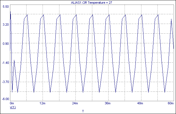
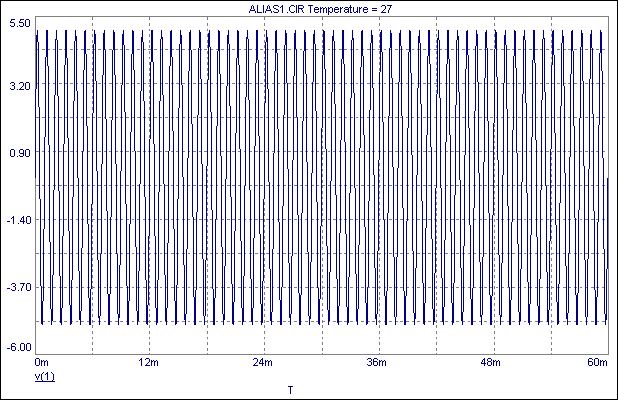
The analysis of this circuit is shown below The simulation has been run for 60ms, and the more cycles of the waveform that are simulated, the worse the aliasing gets. There are no parameters set that force this simulation to take more than the minimum 50 data points, and the results appear extremely choppy with only a vague resemblance to a sine wave. The actual data points produced by this waveform are correct. It is just the interpolation between them that is producing the error. This can be easily seen when looking at the frequency of the waveform. For 60ms, the simulation should be producing 60 cycles, but it appears that only 10 cycles are simulated. The defined frequency of 1kHz now appears to be 166.67Hz. Changing the Maximum Time Step parameter to 6us produces the expected result.
|

|

|
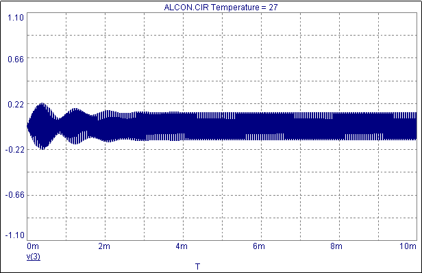
The previous example would be easy to spot upon simulating the circuit with such an obvious disparity in the frequency and the choppy appearance of the waveform. A related problem, undersampling, occurs when the full amplitude of the waveform doesn't propagate through the circuit. The following is an extreme example of this problem.
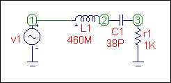
The figure below displays a series RLC circuit. The input source is a sine source which normally protects well against aliasing as it forces the simulation to produce a minimum of 8 data points per cycle. The input source is a 1 volt, 38kHz sine wave. The resonance of this circuit is also at 38kHz. The simulation is run for 10ms producing 380 cycles of the input source.
|

|

|
If the input waveform had been plotted, a quick glance would make it look like the input was working properly. Only upon zooming in on the waveform would a choppy appearance be seen. The frequency would be correct, but the amplitude of the input would be slightly off at .991 volts instead of 1 volt. This small discrepancy doesn't seem like it would cause a big problem, but it appears that when simulating at resonance, the Local Truncation Error algorithms don't adequately control the internal timestep. This behavior can be observed on any SPICE-based simulator. Setting the Maximum Time Step to .1u produces the expected results below. Both of these examples are rare, and the best way to check for this is to view a few cycles of the input waveform to see if it has been sampled as expected.
|
|
|
|
|


