|
|
 |
Phase Locked Loops
How do you do a phase locked loop in Micro-Cap? There are many types of PLLs. Here are some
of them:
APLL: An analog PLL with no digital components operating in the continuous time domain.
DPLL: An analog PLL with a digital phase detector.
ADPLL: An all digital PLL with digital only signals.
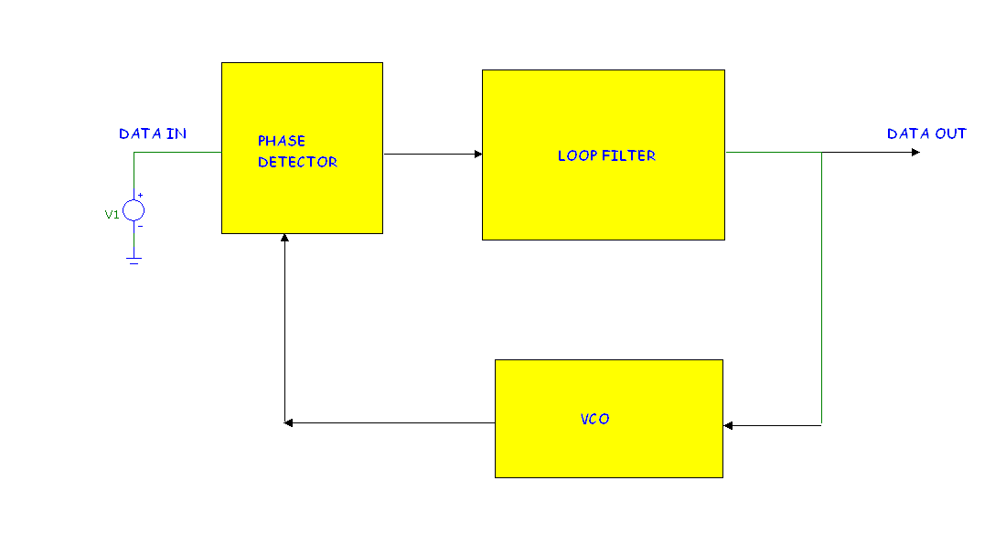
In this article we will cover the first type, the APLL. It uses a block diagram that looks like this:
|

|
Phase Detector: The PLL employs an analog multiplier as a phase detector, often implemented as a
Gilbert cell. In this example we will use a simple macro called the MUL. The MUL multiplier simply
multiplies two signals together. The multiplication produces both sum and difference frequencies
so for input frequencies of say 5K and 5.1K, the phase detector outputs frequencies of 100Hz and
10.1KHz.
Loop Filter: The principal job of the loop filter is to remove or at least minimize the sum
frequency component.
VCO: The job of the VCO is to translate an input DC voltage to a sinusoidal signal.
Here is how the PLL components can be implemented in Micro-Cap. This design is based one at:
http://www.eas.uccs.edu/wickert/ece5675/lecture_notes/n5675_1.pdf...pages 31-33
The phase detector uses the multiplier (MUL) macro which internally looks like this:
The MUL macro is a NFV source whose formula is SCALE*V(PINA)*V(PINB). It multiplies the
two input voltages together and then scales the product by the input parameter SCALE value.
The next component is the loop filter. In this design the loop filter is a concatenation
of a simple low pass filter and an integrator. It looks like this:
The loop filter is implemented, not as a macro, but in discrete form. The transfer function is
approximately this:
1000/(1000+S)*(1+S*TAU1)/(S*TAU2)
Its AC Bode plot looks like this:
|
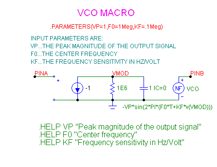
The final component is the VCO macro. It looks like this:

|
This macro is a slightly modified version of the standard VCO macro provided in the Micro-Cap
library. Here we use a -SIN() in lieu of a COS() function. There are three parameters. VP is
the amplitude, F0 is the center frequency, and KF is the scale factor translating input DC
voltage to output frequency.
Here we are using the following VCO parameters.
VP =1
F0=5000
KF=100
So for a VCO input of 0.0 we should get a VCO sinusoid of 5000Hz. If the input moves to 1.0
volts, the output frequency should be:
Fout = F0 + KF*VIN = 5000 + 100*1 = 5100Hz
All of the macros used are available from the Component menu / Analog Primitives / Macros.
The next figure shows the PLL response with an input sinusoid that changes abruptly from 5000Hz
to 5100Hz at T=40ms. We are plotting the input to the VCO which is also the loop filter output.
For T < 40ms the input sinusoid is at 5000Hz and the VCO input eventually arrives at 0.0 volts
causing the VCO output to stabilize at 5000Hz.
For T>=40ms the input sinusoid switches to 5100Hz. The VCO input goes through the complex
adjustment transient shown in the plot causing the VCO output to stabilize at 5100Hz.
|
|
|
|
|


