|
|
 |
FSK System Using a PLL
The PLL can be used in many applications. Here's a circuit that uses the PLL to implement an FSK
system. Its general block diagram is as follows:
|
The heart of the system is the PLL discussed in the first article. The front end looks like this:
|
This is a simple digital data source that drives an analog RC network. Its voltage is used to control an
NFV source with the definition:
.DEFINE FSK IF(V(DATA_IN)<.5,SIN(2*PI*FZERO*T),SIN(2*PI*FONE*T))
The NFV source looks at the analog end of the digital gate and simply switches the frequency
of a sinusoid between 5000 Hz and 5100 Hz depending on the data stream. This creates the FSK
encoded signal that is fed to the PLL input phase detector.
Ideally, if the input frequency is 5000 Hz then the system outputs a "0". If the input
frequency is 5100 Hz then the system outputs a "1".
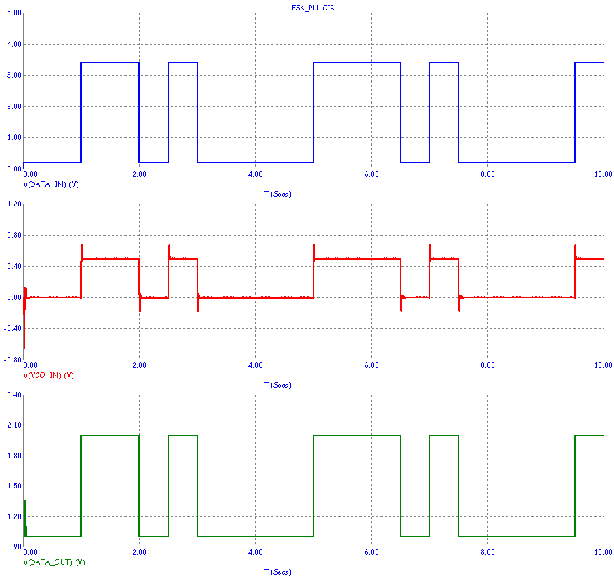
Here is what the output looks like for one input data stream.
|

|
As the FSK shifts frequency to represent the two states, the PLL tracks by changing the
filter output / VCO input voltage, reconstructing the original data waveform. The output
buffer waveshapes the signal, removing overshoot and other noise.
The main part of the filter output signal noise is coming from the sum component of the phase
detector. It can be removed with a stronger filter at the expense of transition time.
|
|
|
|
|


