|
|
 |
Simulating Switched Capacitor Filters
Switched capacitor (SC) filters have come into increasingly common usage. This article will explain a little of the
theory and show how to run simulations on these circuits.
Theory
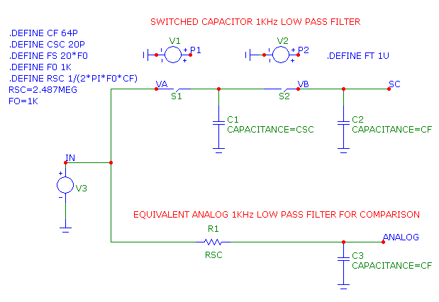
Consider the simple low pass SC filter and its equivalent analog filter circuit shown below.
|
|
When S1 is closed, the capacitor C1 charges to VA. Then S1 opens and C1 holds the charge and voltage. After a
short time, S2 closes and the capacitors C1 and C2 both charge to VB.
The initial charge on C1 is Qinitial = CSC*VA. The final charge on C1 is Qfinal = CSC*VB.
The change in charge on C1 is Qinitial - Qfinal.
dQ = Qinitial - Qfinal = CSC*VA - CSC*VB = CSC*(VA-VB)
The current, averaged over one clock period T is I = dQ/ dT = CSC*(VA-VB)/ T
The effective resistance of the two switches and the capacitor C1 is
RSC = V / I = (VA - VB)/(CSC*(VA-VB)/ T) = T / CSC = 1/ (CSC*FS)
where FS is the switching frequency of the clock. The 3dB corner of this filter is
F0 = 1/(2*PI*RSC*CF) = 994.718
Two important properties of switched capacitors should be now apparent:
Switched capacitors behave like resistors: They can easily create large-valued resistances, which is otherwise very
hard to do in integrated circuits. Resistances larger than 1E6 are easy to create.
Precise control of F0: The 3dB corner frequency is controlled by the clock frequency and the CSC/CF ratio. Both the
frequency and the ratio can be controlled very precisely (better than .1%). Since this is far superior to what can
be achieved with the absolute value of resistors or capacitors, it is a key consideration in using SC filters.
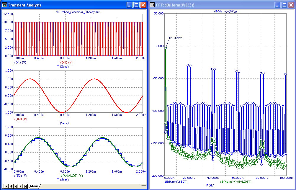
Here is the transient analysis of the circuit and its Fourier spectrum:
|
|
Here we've run two periods of the input sine wave with FIN = F0 = 1kHz, the 3dB frequency of the filter. The bottom plot on
the left shows the output of the SC (blue) and analog (green) filters superimposed. The spectrum plot on the right shows the
dominant component at 1kHz is -3.5 dB, close to what is required at the 3dB point.
There are other frequencies as well. These frequencies, a byproduct of the switching process, are found at n*(FS +/- FIN) with
n=1, 2, 3 ... In this case, the unwanted frequencies are at 19kHz, 21kHz, 39kHz, 41kHz, and so on. If these are a problem in
the design, they can easily be removed with a simple, low tolerance analog filter. It may seem odd to have to use an analog
filter to 'cleanup' after a messy SC filter, but doing so is cheap and easy and still yields a filter with precision control
of its band characteristics.
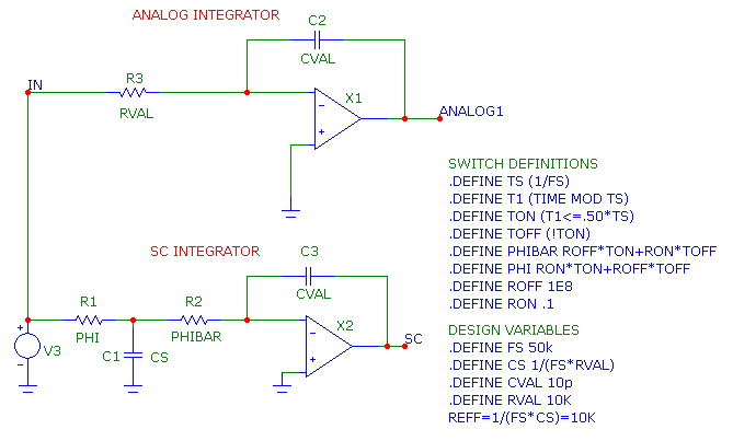
Switched Capacitor Integrator: In this circuit we've built a conventional analog lossy integrator and its SC equivalent.
The SC integrator is built in the same way as its analog cousin but with the resistor replaced with the equivalent SC resistor.
Its capacitance is set equal to 1 / (FS*RVAL), so that its REFF = RVAL. This makes the integrator function in the same way as
its analog counterpart.
|
|
Here we've implemented the switches using the R1 and R2 resistors whose values switch between ROFF and RON
during the half periods of 1/FS. This type of ideal switch exhibits no overlap or nonlinearities. Here is a
transient analysis plot showing both analog and SC waveforms overlaid.
|
BP Filters: Integrators can be used to build band pass filters as in this example. The SC
resistors have been implemented in this circuit as macros.
|
Here is its transient analysis with an input frequency at the center of the pass band, 10kHz.
|
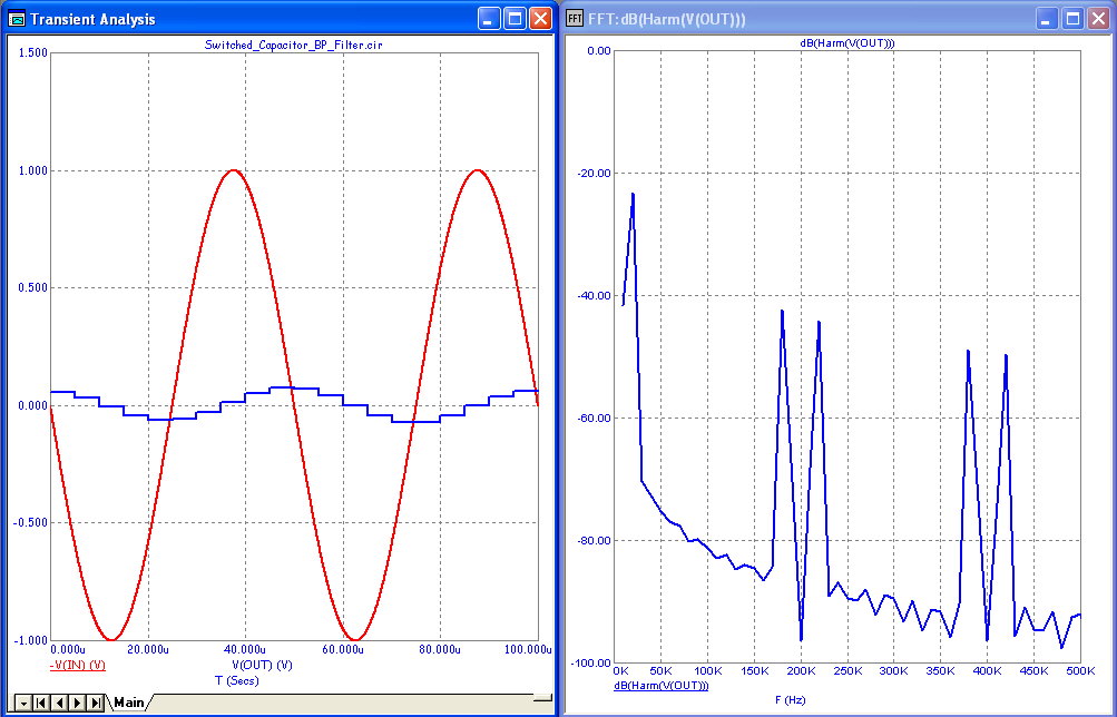
Here is its transient analysis with an input frequency at twice F0 or 20kHz.
|
|
The Fourier plot shows that the gain at the input frequency has declined from 0dB (at 10kHz) to about -23db (at 20kHz), as expected.
Switched Capacitor Guidelines: Here are some important guidelines for successful simulations of switched capacitor circuits.
-) Use the switch macros: Use the simple resistor-defined macro switches first. You can replace them later, if needed, with
more realistic MOSFET switches.
-) Use the simple COMP macro in lieu of an opamp: In these examples we've used the COMP macro where opamps are normally used. It
functions as an ideal opamp with a TANH saturating characteristic. You can replace the COMPs later, once your circuit is working,
with more realistic opamps.
-) Create Design Variables: Use .Define statements for variables like FIN, the input sine wave frequency, FS, the sampling
frequency, F0, the center frequency and so on.
-) Use PSS: Use PSS to calculate the periodic steady state. This eliminates transients and makes the Fourier spectrum plots more
accurate. This is more than useful, it is usually mandatory. If you do not have MC10 and thus cannot use PSS, use the Gear integration
method, set the State Variables to Leave and press F2 repeatedly to get the steady state. Gear is superior to the trapezoidal method
for SC circuits.
-) Keep All Source Periods Commensurable: Make certain that FIN and FS are integer multiples. If they are not, aliasing will
occur, the PSS routines will not work and you will have a mess.
-) Use variables in the analysis limits: In the transient limits use expressions like 1/FIN for the Maximum Time Range and
1E-3/FIN for the Maximum Time Step. This insures that you are always running a multiple number of periods of the input frequency.
If you want finer frequency resolution use 2/FIN or 4/FIN and so on.
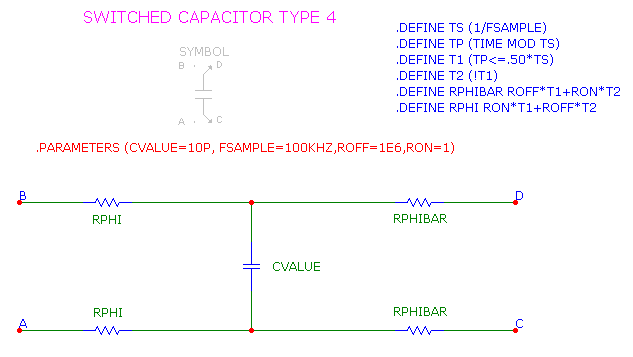
Switched Capacitor Macros: The switch used in this circuit is a macro comprised of the following.
|
|
There are several types of switches used to make SC circuits. This particular one is useful when you need to switch four
pins. The switching behavior is divided into two phases, each 50% of the period of the switching frequency parameter
(FSAMPLE). This parameter is passed to the macro when it is placed in the circuit.
During the first half of the sample period, T1 is TRUE (1.0) and T2 is FALSE (0.0), so RPHI = RON and RPHIBAR = ROFF,
connecting C1 from pin A to pin B.
During the last half of the sample period, T1 is FALSE (0.0) and T2 is TRUE (1.0), so RPHI = ROFF and RPHIBAR = RON,
connecting C1 from pin C to pin D.
Of course you can build the switches in a variety of ways, from simple resistor expressions to MOSFETS driven by two phase
pulse sources. This particular implementation is simple and never overlaps as you change the switching frequency.
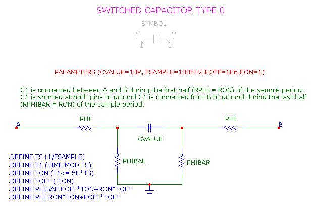
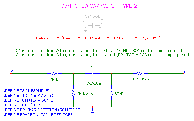
Here are a couple of other forms of switched capacitor macros, SwitchCap, and SwitchCap2.
|
|
|
Here is a 1MHz 3'rd order Elliptic filter that uses these macros.
|
Here is its transient analysis and Fourier spectrum.
|
|
|
|
|


