|
|
 |
Creating Ferrite Bead Models
A ferrite bead is a passive device used to suppress high frequency signals. It is often used to reduce electromagnetic
interference (EMI) or radio frequency interference (RFI) signals within a system. A common equivalent circuit of a ferrite
bead is a lumped element parallel RLC circuit. This circuit produces a reasonable match for the impedance curve of the
ferrite bead. However, a more precise model for the impedance curve can be created by adding a second parallel RLC to
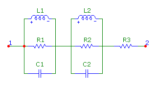
the equivalent circuit along with a series resistance. The modified equivalent circuit is shown below.
|

|
While the equivalent circuit is simple, determining the component values to use to appropriately model a specific ferrite
bead can be onerous. Fortunately, the capability of the Model program to optimize any user created model is designed to
handle such complexity. The first step is to create a basic template of the ferrite bead model. A subcircuit model that
represents the equivalent circuit is defined as:
.subckt Bead 1 2
L1 1 3 1u
R1 1 3 10
C1 1 3 1p
R2 3 4 10
L2 3 4 1u
C2 3 4 1p
R3 4 2 1
.ends
Either a subcircuit or macro could have been used as the template. The advantage to using a SPICE subcircuit in this instance
is that multiple ferrite bead models can then be stored within a single library file.
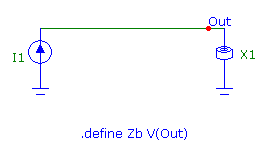
The next step is to create a schematic that simulates an important measurement of the model. For a ferrite bead, the main
specification is the impedance versus frequency characteristic. This characteristic can be easily measured in Micro-Cap through
the schematic below.
|

|
The circuit consists of just a Current Source component and the ferrite bead subcircuit model. The Current Source
component has its AC magnitude parameter set to 1A. Therefore in an AC analysis, the voltage across the ferrite
bead will be equivalent to the impedance of the ferrite bead since:
V = Z*I
I = 1A
V = Z
Also present in the schematic is the following define statement:
.define Zb V(Out)
This define variable is used as an alias. It just maps the expression V(Out) to the variable Zb, so that the AC analysis
can then plot Zb versus Frequency instead of V(Out) versus Frequency. While both would produce the exact same results,
this might help prevent any confusion later when the expression being plotted is used within the Model program.
Next, the analysis limits need to be setup for the AC analysis simulation. For this example, all that needs to be done is to
setup the impedance versus frequency expression to be plotted. On a waveform line, the X Expression is set to F, and the Y
Expression is set to Zb. The impedance of the ferrite bead model is now ready to be optimized in the Model program.
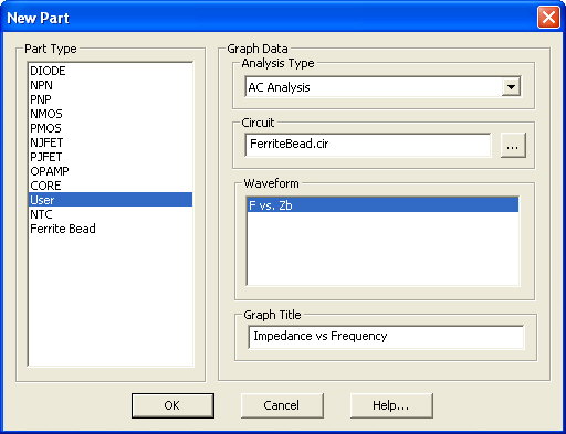
A new model file is created by selecting New from the Model menu. The New Part dialog box will be invoked automatically which
prompts for the device type to specify for the first part in the model file. For a user created part, the part type selected
should be User. At this point, the Analysis Type, Circuit, Waveform, and Graph Title can be specified. The Circuit field
should be set to the test circuit that was created, in this case FerriteBead.cir. Next, the Analysis Type field is
specified as AC Analysis since that was the analysis type used in the test circuit. In the Waveform field, the expression
F vs. Zb is selected. Finally, the Graph Title is defined as Impedance vs. Frequency. This title simply labels the plot
in the Model program. The final settings for the dialog box are shown below.
|

|
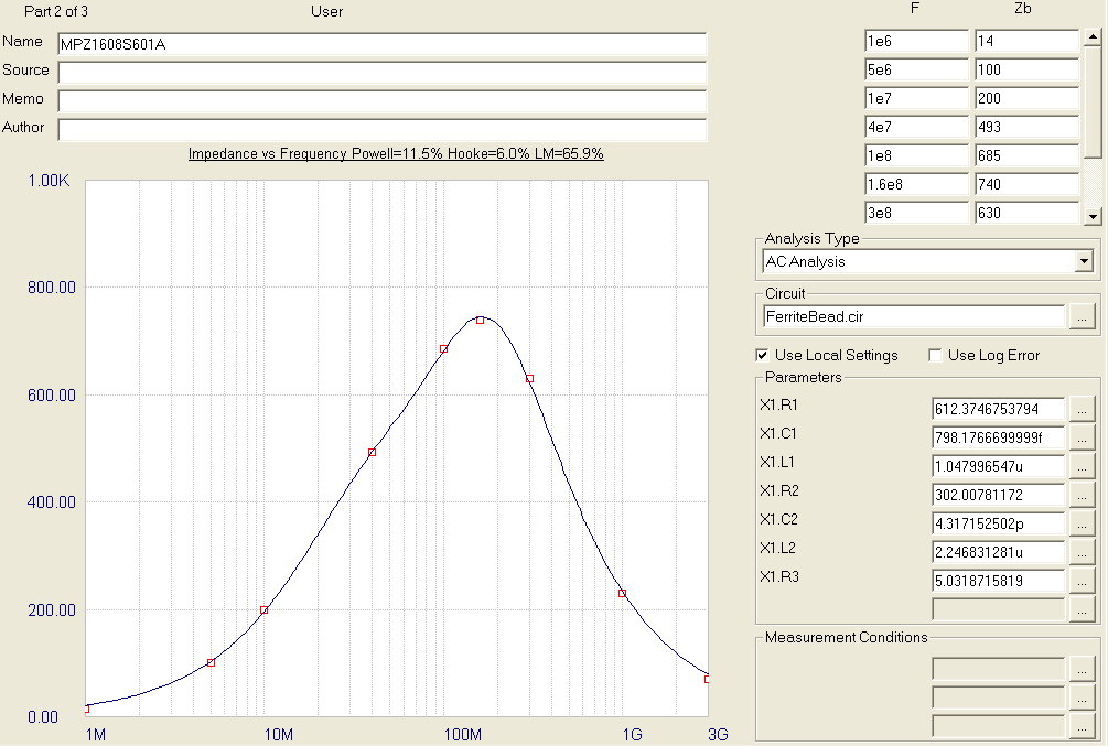
All of the component values in the ferrite bead subcircuit need to be optimized. In the Parameters
section of the model file, the ... buttons can be clicked to add a parameter to be optimized. In the
test circuit, the ferrite bead component has the part name X1, so the following component parameters
are set to be optimized: X1.R1, X1.C1, X1.L1, X1.R2, X1.C2, X1.L2, and X1.R3.
The MPZ1608S601A ferrite bead from TDK was chosen as the device to model. The input data and results for
this device are shown below. As can be seen in the figure, the optimized results produce a good
match to the input data. Using the Create Model for this Part command under the Model menu, the following
subcircuit model is produced.
.SUBCKT MPZ1608S601A 1 2
L1 1 3 1.047996547u
R1 1 3 612.3746753794
C1 1 3 798.1766699999f
R2 3 4 302.00781172
L2 3 4 2.246831281u
C2 3 4 4.317152502p
R3 4 2 5.0318715819
.ENDS MPZ1608S601A
The Save Part to Template Library command under the Model menu can be used to save the current configuration
as a template for easy reuse in optimizing other ferrite bead models.
|

|
TDK also has a SPICE model available for the MPZ1608S601A device. Their model uses a single parallel RLC with
a series resistor. The analysis plot below compares the impedance versus frequency curves for the Micro-Cap
and TDK models. The Micro-Cap model provides a much closer fit to the data sheet curve.
|
|
|
|
|


