|
|
 |
Repetitive Time Switch Macro
The time switch capability available within the Switch component in Micro-Cap provides a
method to define a time range window where the switch will either be open or closed. Only a
single time range may be specified. To specify more than one time window, multiple switches
would need to be placed in a series or a parallel configuration depending on the application. If the
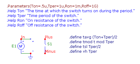
switch opens and closes with a constant duty cycle and period, the switch macro in the figure
below can be used instead. This repetitive time switch macro can be useful in oscillators, timers,
or any other circuit that has a predictable switching time. This macro circuit has many advantages
over using multiple instances of the Switch component. Not only does this macro improve on the
ease of use over using multiple switches, but it also provides smooth transitions during its switching
periods which greatly aids convergence.
|

|
The time switch macro has four parameters that are passed to it: Tper, Ton, Ron, and Roff. The
Tper parameter defines the period of repetition in units of seconds. The Ton parameter defines
the transition point within each time period. For example, if Ton is set to .5u and Tper is set to
1u, the switch will close at .5u, open at 1u, close at 1.5u, open at 2u, etc. Ton must be less than
Tper. The Ron parameter defines the resistance when the switch is closed. The Roff parameter
defines the resistance when the switch is open.
The macro has two pins: Plus and Minus. An S (V-Switch) component models the switch portion
of the macro with its output being between these two pins. This switch has its model defined as:
.MODEL TSW VSWITCH (RON=Ron ROFF=Roff VON=Ton VOFF={Ton-Ton/100})
The RON and ROFF parameters of the switch model are defined using the Ron and Roff parameters
that are passed through to the macro. The VON parameter is defined with the value of the
transition point parameter Ton. The VOFF parameter uses the following equation to define its
value:
Ton-Ton/100
Since the S (V-Switch) has smooth transitions, a transition region must be defined for the model.
When the input voltage to the switch is greater than VON, the switch resistance will be equal to
RON. When the input voltage is less than VOFF, the switch resistance will be equal to ROFF.
The transition region where the resistance of the switch goes between ROFF and RON is defined
by the difference between the VON and VOFF parameters. For convergence reasons, the transition
region should be large enough where at least a few data points will be sampled in this region
during the simulation. For this macro, the transition region has been arbitrarily set so that it is 1/
100 of the Ton value.
Because the S (V-Switch) is actually a voltage dependent switch, the E1 nonlinear function voltage
source has been placed at the inputs to the switch. This NFV source creates a voltage waveform
with the following expression:
(t > ton/2) * (((tmod >= ton/2) AND (tmod < tavg)) * ((vh/tsl)*(tmod-ton/2)) +
(tmod >= tavg) * (vh+(-vh/tsl)*(tmod-tavg)) + (tmod < ton/2) * (ton-2*tmod))
where the tavg, tmod, tsl, and vh parameters are set using define statements as follows:
.define tavg (Ton+Tper)/2
.define tmod t mod Tper
.define tsl Tper/2
.define vh Tper
While it looks complicated, this expression produces a basic triangle waveform whose period is
equal to Tper. The tmod variable which uses the Mod operator sets the periodicity of the waveform.
Its valley voltage is set to 0, and its peak voltage is set to Tper volts. The rise and fall times
of this waveform are set by the variable tsl which is the Tper value divided by 2. During each
period, on the rising edge of the waveform, the source will produce a value of Ton volts at Ton
seconds, with respect to the current period, thus closing the switch. On the falling edge of the
waveform, the source will produce a value of Ton volts every Tper seconds thus reopening the
switch. Some users may wonder why we didn't incorporate a simpler voltage expression to control
the switch such as a sawtooth waveform that can be defined with the expression:
T Mod Tper
While this expression would create a waveform that would toggle the switch at the correct transition
times, it also creates an instantaneous voltage change every Tper seconds. This voltage
change would cause the switch to instantaneously change resistance every time it reopened which
can lead to potential convergence issues. Using the triangle waveform defined above assures a
smooth transition when the switch both opens and closes.
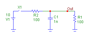
An example circuit using the repetitive time switch macro is displayed in the figure below. When the
switch is closed, the 10V battery charges the C1 capacitor to a value of 5V due to the resistor
divider. When the switch is open, the capacitor is discharged through the R1 resistor. The parameters
of the switch macro have been defined as follows:
Ton = .5u
Tper = 1u
Ron = 1G
Roff = 1m
For each period of 1us, the switch resistance will be set to Roff for the first .5us and set to Ron for
the second .5us. Note that the Ron parameter has been set to 1Gohm and the Roff parameter has
been set to 1mohm. This has the effect of swapping the open and close states for the switch. The
simple rule for this is that when Ron << Roff, the switch will close at the specified Ton time.
When Roff >> Ron, the switch will open at the specified Ton time.
|

|
The transient simulation for this circuit is displayed below. The top waveform shows the
voltage at node Out. As can be seen, the Out voltage is a periodic exponential waveform due to
the charging and discharging of the capacitor. The bottom plot shows the resistance of the switch
in the macro. It is plotted using the expression:
R(X1.S1)
This expression plots the resistance of the S1 switch within the X1 macro. If the View / Data
Points option from the Scope menu was enabled for the plot, it would show that a good sampling
of data points was taken during each of the transition regions of the switch resistance.
|
|
|
|
|


