|
|
 |
Introducing Micro-Cap 9
We are pleased to release the next generation of the Micro-Cap simulator, Micro-Cap 9.0. A
number of new features, components, and models have been added to enhance the simulation
power and the ease of use of the interface. A preview of some of the new features follows. Please
contact our sales department for upgrade or pricing questions.
Models
New BJT, MOSFET, IGBT, and Diode models
A number of new models have been incorporated into MC9.
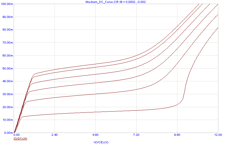
Mextram BJT model - This is a vertical NPN or PNP bipolar model that describes velocity saturation,
base widening, Kirk effect, impact ionization, and self heating effects.
|
|
Modella BJT model - This lateral PNP bipolar model describes current crowding, high-level injection,
and bias dependent output impedance.
PSP MOSFET model - PSP is the latest compact, surface-potential based model suitable for
digital, analog, and RF CMOS applications. Jointly developed by Philips and Penn State University,
the model accounts for mobility reduction, velocity saturation, DIBL, gate current, and lateral
doping gradient effects.
Philips MOSFET Model 11 - A popular Philips MOSFET model suitable for low voltage CMOS
RF applications.
Philips MOSFET Model 20 - A high voltage compact LDMOS model.
Philips MOSFET Model 31 - A high voltage MOSFET model.
Philips MOSFET Model 40 - A high voltage Silicon-On-Insulator (SOI) MOSFET model.
Hefner IGBT model - An integrated IGBT model was added. It is based upon the implementation
by Gregory Oziemkiewicz of the Hefner model.
JUNCAP and JUNCAP2 diode models - These diode models are used in conjuction with
MOSFETs. JUNCAP2 is a MOSFET pn junction model that describes depletion capacitance,
Shockley-Read-Hall currents, trap-assisted tunnelling and band-to-band tunnelling, avalanche
breakdown, and shot noise.
New IBIS components
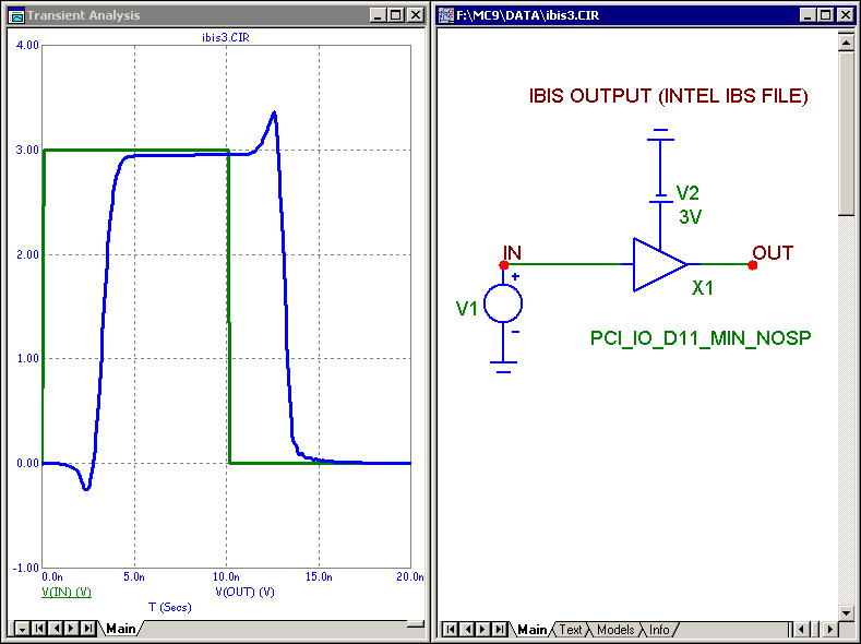
New IBIS components have been added that ease the importation of IBIS models into a simulation.
These components can be placed in a schematic and assigned a pin from an IBIS file. It
creates the appropriate model at that point and is ready for simulation.
|
|
N-Port component
ABCD and T parameters may now be used with the N-port components.
Enhanced RLC models
Resistors, capacitors, and inductors now have optional model parameters for parasitic resistance,
capacitance, and inductance.
User source
A trigger expression was added. The source is idle until the expression becomes true.
Digital file stimulus source
Added a repeat capability to the source.
Analysis
Enhanced convergence methods
The Junction GMIN Stepping and Pseudo Transient methods were added to the arsenal of operating
point methods. There are now five methods:
Standard Newton-Raphson
Source Stepping
Diagonal Gmin Stepping
Junction Gmin Stepping
Pseudo Transient
Means were added to select the preferred order of usage and to automatically search for the fastest
of the methods.
RSHUNT, CSHUNT, and RP_FOR_ISOURCE global parameters were added to provide augmented
convergence. These parameters add an RSHUNT resistance or CSHUNT capacitance from
every node to ground, or an RP_FOR_ISOURCE resistance across any current source.
Dynamic analysis mode
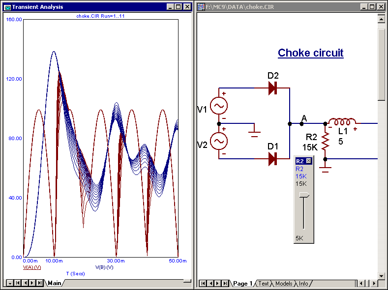
A new interactive analysis mode allows dynamic plot updates as changes are made. This is an
extension of Dynamic DC to transient analysis, AC analysis, and DC analysis. Plots can either
accumulate or replace showing the effect of successive changes in component parameters, model
parameters, or user variables. Parameter changes can be controlled by sliders, cursor keys, or edits
of any kind.
|
|
Dynamic performance tags
These new tags perform curve measurements showing the new values each time an analysis is run
or a new branch of a stepped curve is selected.
Plot pages
Analysis plot pages with assignable names allow plot grouping in different windows.
Waveform buffer
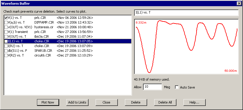
A new Waveform Buffer stores curves / waveforms automatically or under user control for later
plotting and comparison. The buffer provides a convenient method for importing/exporting
waveforms into any analysis.
|
|
Numeric output improvements
Variable engineering notation within a column of numbers, selectable row/column tabular format,
and curve aliases were added to numeric output files. Printing can be limited to a subset of the
simulation range. Numeric output is now available for Dynamic AC and Dynamic DC.
New wildcard syntax for plot expressions
A new wildcard syntax is available for use in the Y Expression field of the Analysis Limits dialog
boxes. This syntax allows the user to compactly specify the plotting of many similar expressions.
Define variable usage
.Define variables can now be used in the X and Y Range fields, the Maximum Time Step, and in
the FFT Upper and Lower Time Limit fields.
Envelope command
This new command creates a polygon encompassing the curves of a Monte Carlo or stepped run. It
is useful for graphically depicting the plot variation.
Visible region auto-scale
A new auto scale command is available that operates only over the X portion being currently
displayed on the screen.
Additional analysis features
Added RMS and Average performance functions.
Added a data point only waveform style.
Cursors can now be placed on separate curves.
The numeric format can now be set individually for each tag.
The Save Curve command can now save in CSV format.
Stepping tabs are now check-marked if they are active.
Probe
Edit while probing
The interactive analysis feature of MC9 lets you edit the schematic while in probe. Each edit
updates the simulation and shows the effect of the change. CTRL + SPACEBAR cycles through
the available probe modes, while SPACEBAR now toggles between probe mode and schematic
select mode.
Visual probing of macros and subcircuits
Drill down probing lets you visually probe macro schematics or subcircuits to any level. Instead of
selecting items from a list, you can probe macro objects directly. With subcircuits, you can probe
directly on netlist nodes and names.
Expanded Probe displays
FFT, Performance, and 3D Windows are now available in Probe.
Schematic Editor
Window tabs
Window tabs allow easy access to open shematics, plots, histograms, performance windows, etc.
Circuitry region enable / disable
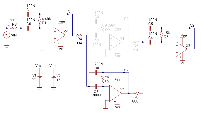
Circuitry can be temporarily enabled or disabled with a simple click, allowing multiple versions of
a circuit to be contained in a single schematic. Disabled regions are ignored during an analysis.
Whole pages or regions within pages can be controlled.
|
|
Region enable expressions
A new Region Box with an enable expression allows conditional inclusion of circuitry.
Schematic display
On-schematic display of last, RMS, average, or peak values.
Macro embedding
The Localize command now embeds external macro files into the circuit, for better file portablity.
Component panel
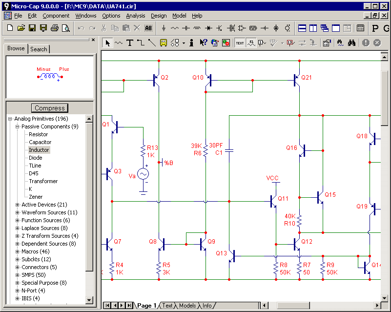
The component panel provides easy access to the component library for placing parts in a schematic.
It has the capability to browse through the component tree or to quickly search for specific
parts.
|
|
User-assignable hotkeys
Users can set their own hotkeys for any command.
Multiple shape capability
Components can now have multiple shapes assigned to them. Each shape has a shape group as
well as a shape name, allowing easy switching between shape families.
Warning messages
Parts and nodes involved in a triggered warning are now colored. The command has been improved
with the addition of global names like R@ to refer to any and all resistors. Warning messages
are now also sent to the numeric output file.
Text control blocks
New text control blocks (.IF boolean_expression, .ELSE, .ELIF boolean_expression, and
.ENDIF) allow conditional inclusion of text, which may control .commands, model statements,
and SPICE netlist circuitry.
.SPICE / .ENDSPICE commands
These new commands let you add SPICE netlist-defined circuitry to the text pages of schematics
without using a subcircuit.
Intelligent Paste command
A paste between circuits optionally adds the appropriate model statements, subcircuits, and
macros to the new circuit.
Bus
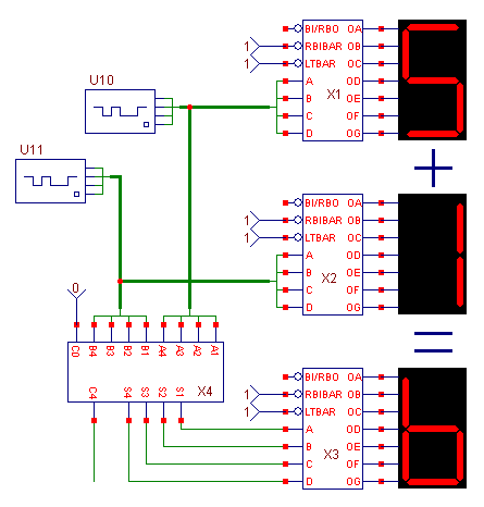
A bus connector and associated wiring routines were added.
|
|
Assignable component links
Components now have a user-assignable link for quick access to data sheets or other technical
documents from an internet URL or a disk location.
Live text expressions
Expressions can now be buried in grid text and are updated as the constituent variables change.
Fit to Standard Values command
This finds the closest single or series/parallel combination of standard part values that match a
given R, L, or C value.
RGB color stored in file
RGB color information (rather than a palette number) is now stored in the circuit file so when the
circuit is given to someone else, the colors stay the same.
Additional schematic improvements
Improved Component Find searches as you type.
Parameter Find command now available in the Attribute dialog box.
Common patterns are now button selectable for the digital stimulus source.
Rubberbanding now eliminates all diagonal lines.
Multiple attributes of a component can be moved together.
A delimiter can now be specified for the Bill of Materials export.
Multiple circuits can be assigned a password simultaneously.
Next Object command lets you select overlapping objects.
Parameters can now be passed to a circuit through a batch file.
Node Snap and Text Increment have been assigned hotkeys.
Element information is displayed at the mouse cursor in the schematic.
Monte Carlo
New Tolerance dialog box
This provides a rapid way to apply LOT and DEV tolerances. Tolerance templates can be saved
and applied to future models.
Improved Load MC File command
A Load MC file dialog box lets you choose which of the cases you want to load for review.
Performance measurement display
Selecting a case from the Histogram display list while the plot is in Cursor mode causes the corresponding
performance function measurement to be shown.
Filter Designer
Passive elliptic filters
Passive elliptic filter capability was added.
Fit to Standard Values command
A new command was added to find the optimal series or parallel arrangement of standard resistors,
capacitors, and inductors.
Expressions
Arrays were extended to handle multiple dimensions and complex values.
FFTS and HARM functions now have an optional bandwidth parameter.
Complex impedance and conductance expressions are available in AC for passive elements.
Legendre polynomials were added.
The Lambert W function was added.
The limiting exponential functions EXPL and EXPLP were added.
Component Editor
Right click menu lets you add, copy, delete, paste, replace, and find information for parts.
Can now delete groups that contain parts.
Move Parts command can now select the From group as well as the To group.
Add Part Wizard now lists the available models in the selected files.
Added an option to initially display the macro parameters when the part is placed in a schematic.
Miscellaneous Improvements
An enhanced migrate command now handles macro and library files.
Recently used component list size is now user adjustable.
Find in Files command now searches text in analysis limits and plots.
File dialog boxes retain the view settings. Windows XP or later.
|
|
|
|
|


