|
|
 |
Measuring Insertion Loss
Insertion loss, often used within telecommunications design, is a means of determining the terminal
attenuation that results from inserting a device into the signal path. It is measured as the ratio of the
signal power delivered to the terminal prior to insertion versus the signal power delivered to the
terminal after insertion. The following example consists of a two port filter that is operated between
a resistive source and a resistive load. In this case, the insertion loss is calculated by comparing the
power dissipated in the load resistor before the filter is inserted to the power dissipated in the load
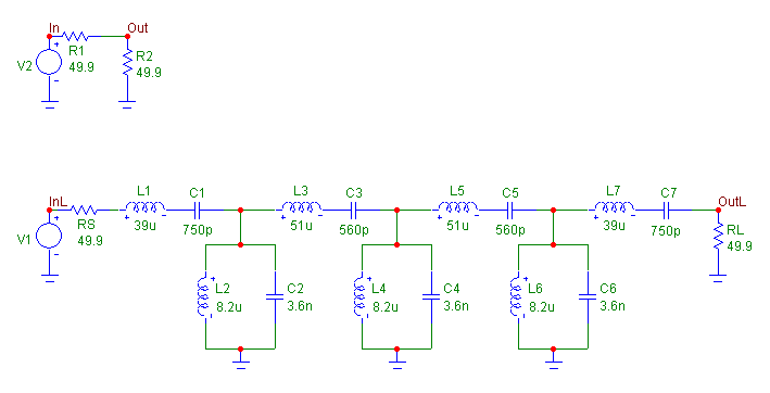
resistor after the filter is inserted. The example schematic is displayed in the figure below.
|

|
This schematic actually consists of two circuits. The circuit on top represents the state before the
insertion of the filter, and the circuit on the bottom represents the state after the insertion of the filter.
Both circuits use a Voltage Source component as their input. These two sources need to be defined
with the same values. In this case, the AC magnitude value has been set to 1, and the AC phase and
DC values have been set to 0.
The filter inserted into the signal path was created from the Passive Filter Designer in Micro-Cap. The
filter is a passive bandpass Chebyshev dual implementation. It was created with the following
characteristics:
Center Frequency = 1MHz
Passband Frequency = .7MHz
Stopband Frequency = .8MHz
Passband Gain = 0dB
Passband Ripple = 3.01dB
Stopband Attenuation = 20dB
The power dissipated in the load resistors must be compared to each other. A way to simplify the
expression is shown as follows:
PB = V(Out)^2 / 49.9 = Power dissipated in the load resistor before insertion
PA = V(OutL)^2 / 49.9 = Power dissipated in the load resistor after insertion
Ai,Np = .5*ln(PB/PA) = ln( |V(Out)/V(OutL)| )
Ai,dB = (20/ln 10) * Ai,Np
Ai,dB = (10*log(PB/PA))
Ai,dB = 20*log( |V(Out)/V(OutL)| )
Ai,dB = dB(V(Out)/V(OutL))
For a resistive load, insertion loss reduces to the simple expression dB(V(Out)/V(OutL)), which
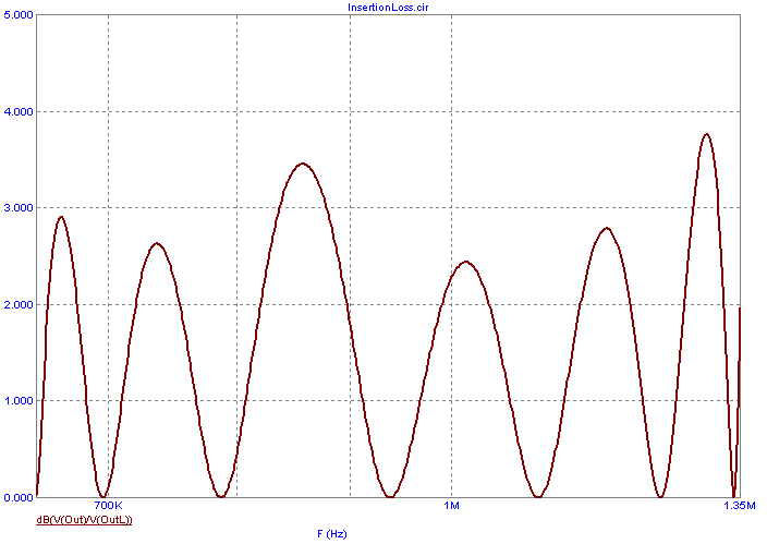
calculates the ratio of the voltages across the two load resistors in dB. The insertion loss plot for this
filter is shown in the figure below.
|

|
The plot was created through an AC analysis that simulates the frequency range across the passband
region (650kHz to 1.35MHz) of the filter. For this example, since the passband gain of the filter was
0dB, the insertion loss measurement across the passband region is due to the passband ripple of the
filter.
|
|
|
|
|


