|
|
 |
RMS Macro
The root mean square calculation provides a method to statistically measure the magnitude
of a varying waveform. Micro-Cap provides an RMS operator that can be used to plot the
root mean square value of any specified waveform. However, the RMS operator can only be
used for plotting waveforms in an analysis as it is not available for use in expressions
within the schematic. For an instance where a component such as a switch needs to be
triggered by an RMS value, circuitry would need to be added to perform the measurement in
the schematic. One macro circuit configuration for calculating an RMS value is displayed
below.
|
For a continuous function over the time range T1 to T2, the equation for the root mean
square calculation is as follows:
|

|
The macro circuit is designed to model this equation. The nonlinear function voltage
(NFV) source, E1, squares the voltage at node In. The squared voltage is then fed into
an Int macro which performs the integration calculation. For the RMS macro, the T1
parameter from the above equation will be defined as 0 which is the typical value most
simulations start with. Since this macro produces a running root mean square value,
the T2 parameter will be the time that is currently being analyzed. The output of the
integrator is then referenced by the E2 NFV source in the following equation:
sqrt(V(IntOut)/T)
This expression takes the output voltage of the integrator and divides by the current time
of the simulation. The T variable can be used in place of T2 - T1 due to the assumption of
T1 being 0. Finally, a square root operator is applied to produce the final RMS value.
Due to both the divide by T and the integration within the RMS circuit, any transient
simulation using this macro should have its Operating Point option disabled in the Transient
Analysis Limits dialog box.
For circuits, one of the common uses of the RMS calculation is to calculate the power
dissipation in individual components when the current and voltage are varying functions. An
example circuit using the RMS macro appears below in which the macro is used to
calculate the RMS power of the load resistor.
|

|
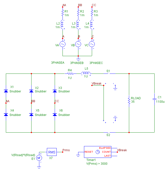
The circuit contains a typical three phase power supply. A six pulse diode rectifier is
used as an AC to DC power converter to produce a DC voltage at the load of the circuit.
The power through the load resistor will peak during the initial transient of this
circuit. To help protect the load, a switch has been connected on each side between the
load and the six pulse diode rectifier. These switches will be triggered based on the
RMS power dissipated by the load resistor. The E1 NFV source calculates the instantaneous
dissipative power of the resistor with the following expression:
V(Rload)*I(Rload)
The value of the instantaneous power is then used as the input into the RMS macro. The
RMS power of the load resistor is equivalent to the RMS macro's output voltage at node
Prms. Since the switches should stay open once they are triggered, they do not reference
the voltage at the output of the RMS macro directly. Instead a Timer component is used to
trigger the switches. The Timer component has its INPUTEXPR attribute defined as:
V(Prms) > 3000
which will count each instance that the voltage at node Prms exceeds 3000 volts. The two
switches share the same model statement which is defined as follows:
.MODEL LOADSW VSWITCH (RON=1m ROFF=1e6 VON=.2 VOFF=.8)
When the input voltage to the switch is below .2V, the switch is on, and when it is above
.8V, the switch is off. The input voltage to the switches is the voltage at the Count pin
of the timer. The Count pin keeps track of the number of events that occur defined by the
INPUTEXPR attribute. This pin will initially be set to zero volts at the beginning of the
simulation so that the switches are on. The first time that the voltage at Prms becomes
greater than 3000V, the Count pin voltage is incremented to one volt which will turn off
the switches. Since the Reset pin of the Timer is grounded, the voltage at node Count
will only increase or stay the same so the switch will remain open for the remainder of
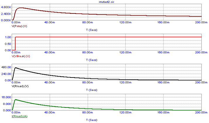
the simulation. The transient analysis of this circuit is shown below. Again note
that the Operating Point option has been disabled for the RMS macro to operate correctly.
|

|
The top plot displays the output voltage of the RMS macro. The second plot displays the
voltage at the Count pin of the Timer. Note that when the RMS power exceeds the 3000 limit
set in the Timer that the voltage is incremented from zero to one thus turning off the
switches. The bottom two plots show the voltage and the current through the load resistor
respectively.
|
|
|
|
|


