|
|
 |
Amplitude Modulator Macro
Amplitude modulation plays a key role in many types of communication systems, the most
obvious one being AM radio. In amplitude modulation, a message signal is shifted to a
high frequency carrier signal whose frequency coincides with the necessary transmission
requirements. The amplitude of this carrier signal is modulated depending on the
strength of the message signal.
The usual amplitude modulation is double sideband modulation. In this type of
modulation, a DC signal is added to the message signal prior to using it to modulate the
carrier signal. Double sideband modulation typically carries the form of:
Vs(t) = Vo*(1 + m*Vm(t))
where Vo is the DC offset, m is the modulation index, and Vm(t) is the message signal.
The modulation index should be set to a value in the range from zero to one where m=0
represents no modulation and m=1 represents a maximally modulated signal. This modified
message signal is then multiplied by the carrier signal to get the final modulated signal
such as:
Vmod(t) = Vs(t) * Vc(t)
where Vc(t) is the carrier signal which is typically a sinusoidal waveform.
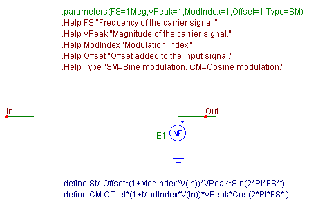
The macro model for the amplitude modulator is shown below. The macro circuit consists of
only a nonlinear function voltage source, E1, which performs the mathematical computations
of the modulation. There are five input parameters for this macro: FS, VPeak, ModIndex,
Offset, and Type. The FS parameter defines the frequency of the sinusoidal carrier
signal. The VPeak parameter sets the peak amplitude of the carrier signal. The ModIndex
parameter defines the modulation index, and the Offset parameter sets the offset value
that is added to the input signal. These parameters correspond to m and Vo, respectively,
in the Vs(t) equation above. The Type parameter determines whether the carrier signal
will be a sine or a cosine function.
|

|
The most interesting aspect of the macro is the use of the Type parameter. The VALUE
attribute of the E1 nonlinear function voltage source has been defined as Type. In the
circuit calling the macro, the Type attribute must be defined as either SM for sine
modulation or CM for cosine modulation. When an analysis is invoked, either SM or CM
will then be substituted into the VALUE attribute of E1 in place of the Type declaration.
Define statements within the macro circuit set the equations that are assigned to SM and
CM as follows:
.define SM Offset*(1+ModIndex*V(In))*VPeak*Sin(2*PI*FS*t)
.define CM Offset*(1+ModIndex*V(In))*VPeak*Cos(2*PI*FS*t)
These equations determine the actual modulation expression that will be used. The only
difference between the two expressions is that the SM variable uses a sine wave as the
carrier waveform, and the CM variable uses a cosine wave. Setting the Type variable to
any value besides SM or CM in the calling circuit will produce an error. However, this
method is easily expandable if the function source is capable of handling the new
expression. For example, if a basic amplitude modulation was needed, a new define
statement could be added to the macro such as:
.define BM V(In)*VPeak*Sin(2*PI*FS*t)
Then BM would become a valid setting for the Type parameter and would invoke the
specified expression.
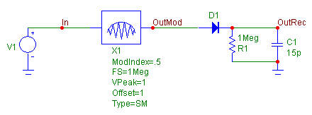
An example circuit using the amplitude modulator macro is displayed below. The input to
the macro is a 1V, 20kHz sine wave. The macro has its parameters defined as:
FS = 1Meg
VPeak = 1
ModIndex = .5
Offset = 1
Type = SM
The carrier signal is defined as a 1V, 1MHz sine wave. The input signal will be offset
by 1V and will use a modulation index of .5. The output of the modulator is then sent to
a simplified AM receiver which is essentially acting as a peak detector.
|

|
The resulting transient analysis is shown below. The waveform V(OutMod) is the signal
at the output of the modulator. The information in the modulated signal is carried in
the envelope of the waveform. The waveform V(OutRec) is the signal at the output of the
receiver. With the simple AM receiver, there is some distortion with the carrier ripple
on the rising edge of the waveform, but it is a good overall representation of the
adjusted sine wave that was input to the modulator which shows why the peak detector
method of retrieval is widely used. More elaborate receivers would of course have
tuners, filters, level shifters, and gain stages to more fully reproduce the input
signal.
|
|
|
|
|


