|
|
 |
Hysteresis Switch Macro
A hysteresis switch can be used in multiple applications such as oscillators or undervoltage-lockout
systems. The switch primitives that are available in Micro-Cap 7 don't have hysteresis capabilities
built into the models. In order to add this capability to one of the switches, a new macro circuit
needs to be built using a switch primitive with added circuitry to handle the hysteresis. The macro
and example circuits used in this article were derived based on a Christophe Basso article titled
"Inline Equations Offer Hysteresis Switch in PSpice" that appears in the August 16, 2001 issue of EDN.
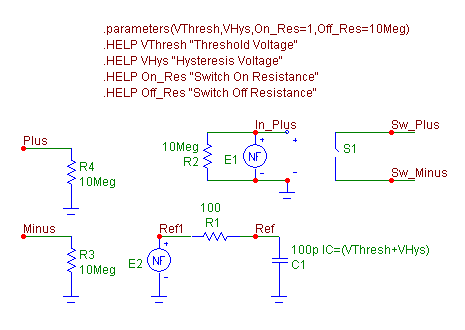
The hysteresis switch macro circuit appears below.
|

|
The macro circuit has four input parameters: VThresh, VHys, On_Res, and Off_Res. The VThresh parameter
defines the threshold voltage for the switch. The VHys parameter defines the hysteresis voltage that
will be used with the threshold voltage to define the two toggling points. The high toggling point will
be calculated as VThresh + VHys, and the low toggling point will be calculated as VThresh - VHys. The
On_Res and Off_Res parameters define the on and off resistances for the switch.
The Plus and Minus nodes are the two voltage sensing input nodes for the macro. Each of these nodes
has a 10Meg resistor going to ground to provide a high input resistance. The Sw_Plus and Sw_Minus
nodes are the two output nodes of the macro and are on the outputs of a switch component. The switch,
S1, in the macro is the S (V-Switch) component and is defined with the following model statement:
.MODEL SMOOTHSW VSWITCH (RON=On_Res ROFF=Off_Res VON=1 VOFF=0)
This voltage switch has a smooth transition when the voltage across its input nodes transitions between
the VON and VOFF values. When the voltage is greater than VON, the resistance of the switch will be
RON. When the voltage is less than VOFF, the resistance of the switch will be ROFF. In this case, a
voltage of 1V or greater at the input will close the switch, and a voltage of 0V or less will open the
switch. Between 0V and 1V, there is a smooth transition of the switch resistance between its on and
off states in order to aid in convergence. The two resistance values for the switch are defined by the
On_Res and Off_Res parameters that are passed into the macro. The input nodes of the S1 switch sample
the voltage of the E1 nonlinear function source. The E1 source has its VALUE attribute defined as:
If((V(Plus)-V(Minus)) > V(Ref), 1, 0)
The E1 source compares the differential voltage at the input nodes of the macro to the voltage at the
node Ref in the macro circuit. If the input voltage is greater than the Ref voltage, the source
produces a 1V output which closes the switch. When the input voltage is less than the Ref voltage,
the source produces 0V which opens the switch.
The voltage at node Ref stores the toggling point of the switch. When the switch is open, the voltage
at node Ref is equal to the high toggling point voltage, and when the switch is closed, the voltage at
node Ref is equal to the low toggling point voltage. The difference between the two toggling points
creates the hysteresis effect. The E2 nonlinear function source detects whether the switch is open or
closed and produces the corresponding toggling point voltage. The VALUE attribute for the E2 source
is defined as:
If(V(In_Plus) > .5, VThresh-VHys, VThresh+VHys)
If E2 detects that the voltage at node In_Plus is greater than .5V (closed switch), the source produces
the low toggling point voltage (VThresh-VHys), and if the voltage at node In_Plus is less than .5V
(open switch), the source produces the high toggling point voltage (VThresh+VHys). The resultant voltage
is then stored at the Ref node on the C1 capacitor after a small RC time constant. The C1 capacitor
has its initial condition arbitrarily set to the high toggling point.
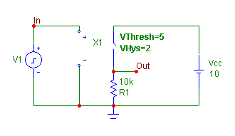
Two example circuits have been created to test the hysteresis switch macro. The first circuit appears
in below. This circuit is designed to display the basic Vout vs Vin curve of the switch. The switch is
placed in series between a battery and a resistor. The VThresh parameter is defined as 5V, and the VHys
parameter is defined as 2V. The input of the switch is placed across a pulse source that creates a 10V,
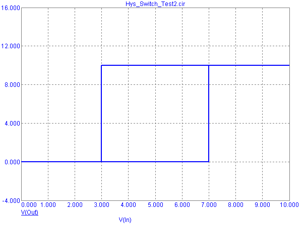
2ms triangle wave. The transient analysis of this circuit appears below also. The analysis displays the
traditional hysteresis waveform with the expected transition points at 3V and 7V, confirming the plus or
minus 2V hysteresis.
|

|

|
The second circuit is a simple RC oscillator and appears below. Again, the switch parameters
have been set as VThresh=5V and VHys=2V. The transient analysis of the circuit also appears below.
Note that the toggling points of the oscillator are at the expected 3V and 7V. In both of the example
circuits, the on and off resistances of the switch were kept at the default values defined in the macro
circuit .parameters statement.
|
|
|
|
|


