|
|
 |
Simulating the Multiplier Parameter in BJT Models
The M parameter lets you model devices that are parallel combinations of smaller "unit" devices. If the model parameters of the "unit" device are known, then the model parameters of the larger aggregate device can be easily be specified.
MC6 and MC7 have an M multiplier parameter for the MOSFET but not for the BJT. Here is a method for implementing such a multiplier.
Make a circuit with the BJT in it. Add the following symbolic definition statement to the circuit:
.DEFINE M 1.0
This creates the symbolic variable, M and assigns it a nominal value of 1.0.
Now make the following edits to the indicated BJT model parameters:
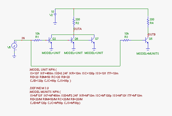
1) Divide the resistance-related terms by M (RB, RBM, RE, RC)
2) Multiply the current-related terms by M (IS, ISS, IKF, ISE, IKR, ISC, ITF)
3) Multiply the capacitance-related terms by M (CJE, CJC, CJS, TR, TF)
Now the variable M can be edited to reflect the number of parallel devices. Here is a circuit that compares using a set of three "unit" devices connected in parallel at OUTA and a circuit using a "multiplied" device with the M value set to 3.0 at OUTB.
|

|
Here is the transient analysis of the circuit showing plots of the two outputs OUTA and OUTB. The plots are identical indicating that the BJT with a "multiplier" of 3.0 is equivalent to three "unit" devices in parallel.
|
As an additional check, here is the AC analysis. The gain and phase plots are identical and coincident, indicating complete equivalence between the two circuits.
|
|
|
|
|


