|
|
 |
Plotting Loop Gain and Phase Margin
Circuit stability
What is stability? How do you determine if a circuit is stable? A circuit is unstable if it spontaneously starts oscillating in the presence of noise alone. Consider a typical, three-pole circuit show below.
|
|
If you run this circuit in transient analysis, it will produce the following plot.
|
In this circuit the input is a one volt damped sine wave programmed to simulate a noisy spike. When the value of the last capacitor, CC, is 40pF, the circuit is stable as can be seen from the damped oscillation on the output.
What happens when we changed CC?. If the value of CC is changed from 40pf to 80 pf, the result is much different. As Figure 3 shows, the circuit now produces undamped oscillation.
|
This is one way to test for circuit stability. The other way is to examine the loop gain and use the phase margin test.
Loop gain
Knowing the loop gain of a closed-loop feedback system is essential to understanding its stability properties. It is easy to plot open loop gain. You simply place an AC source at the input and plot the signal value at the output. But what about loop gain? How do you get that? First, a little review.
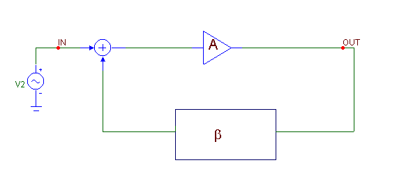
The general feedback circuit sketched below produces a loop gain of A*b.
|
|
Stability requirement
Stability requires that the loop gain phase angle should be greater than -180 degrees when the loop gain is 1.0.
Phase margin is the amount by which the phase angle exceeds -180 degrees when the loop gain is precisely 1.0
Phase margin = Phase Angle - (-180) = Phase Angle + 180.
Phase margin measures the circuit's stability, or in other words, its susceptibility to oscillations.
If the phase margin is, say 10 degrees, the circuit will not oscillate and any noisy disturbance on the input will produce, at most, a damped oscillation. If the phase margin is exactly 0, the circuit will oscillate at a steady amplitude. If it is, say, -10 degrees, the circuit will break into undamped oscillations which eventually will be limited to whatever the power supplies dictate. In general designers strive to achieve the following.
Phase margin rule
Keep the phase margin greater than 45 degrees.
As circuits age, their components will vary, possibly pushing a marginal circuit into instability. Phase margin quantifies the safety margin the circuit has to such variations.
Breaking the loop:
To measure loop gain and its phase we must break the loop. The loop must be broken only in an AC sense, as the DC or biasing circuitry must be allowed to operate. The trick to doing this is to strategically place large valued inductors and capacitors to close the loop for DC (low frequency bias) signals and open the loop for AC (higher-frequency) signals. Rosenstark (1986) developed the following formula:
Loop Gain = -1 / (1/Toc+1/Tsc)
Toc = open circuit voltage gain = V(VOC) / 1 = V(VOC)
Tsc = short circuit current gain = 1/I(VSC) / 1 = 1/I(VSC)
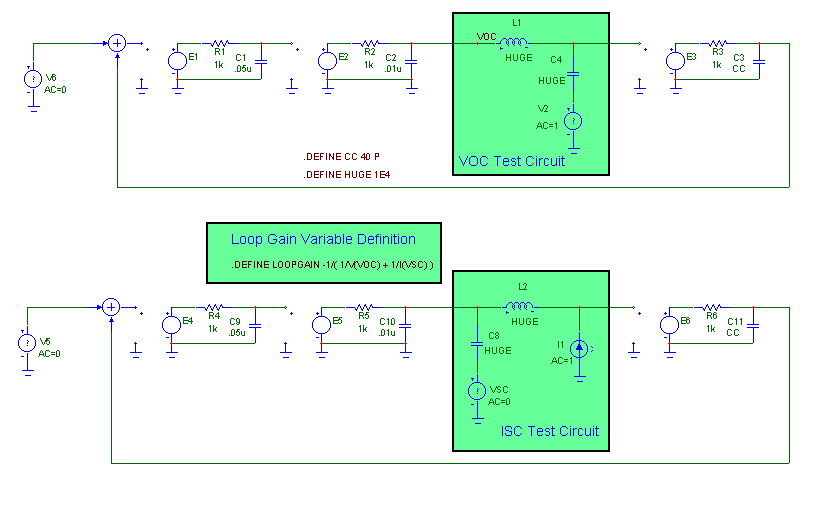
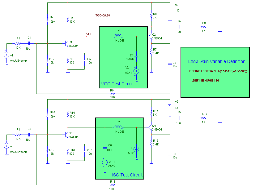
All we need do is measure Toc and Tsc and plot the Loop Gain function. The following circuit
|
|
uses two copies of the three-stage feedback circuit of Figure 1. One copy is used to measure Toc, the loop voltage gain and the second circuit measures the Tsc, the short circuit gain. The symbolic variable LOOPGAIN embodies the loop gain formula and provides a convenient plot variable.
This is the general procedure for testing loop gain on an arbitrary circuit:
1) Set the AC magnitude of all of the original sources to 0. Copy the circuit to be tested (DUT) to the clipboard. (CTRL+A then CTRL+C).
2) Make a new circuit and paste two copies of the DUT (CTRL+V) from the clipboard to the new circuit. The first copy is for measuring Toc and the second copy is for measuring Tsc.
3) Break the loop of the first copy and insert a large AC loop breaking inductor (L1) and a large capacitor (C4) that AC 'shorts in' the 1.0 VAC input test source (V2). Add the Voc text label the point where the open circuit voltage will be measured.
4) Break the loop of the second copy and insert a large AC loop breaking inductor (L2) and a large capacitor (C8) that AC 'shorts in' the 0.0 VAC output current measuring source (VSC). Add the 1 Amp AC input current source (I1).
5) Add the LOOPGAIN define statement text as shown in Figure 5.
6) Run AC and plot dB(LOOPGAIN) on plot 1 and PH(LOOPGAIN) on plot 2.
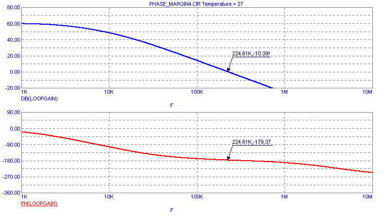
7) When the run is done, invoke the GoTo Y command (SHIFT + CTRL+Y), type in 0 in the Value box. Click on the Left button, then on the Close button. The left cursor will be positioned on the 0 dB point of the gain curve and at the corresponding frequency point on the phase curve.
8) Read the phase in the "PH(LOOPGAIN)" plot as -178.37 degrees. The circuit is barely stable with less than 2 degrees margin of safety.
|
|
|
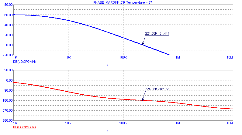
What happens when we increase CC to 80 pF? Here is what the plot looks like:
|
|
The phase margin is -1.55 degrees so the circuit is unstable. By experimenting with the CC value you can determine that the actual crossover from stability to instability in this circuit occurs when CC is between 60pF and 61 pF.
Helpful hints
Where do you break the loop? In this circuit it does matter much, but in general the loop should be broken such that the V(VOC) measurement can be made where the circuit has a low output impedance.
The Sine and Pulse and User sources all have a fixed AC magnitude of 1.0, so you cannot use them at the usual input since their AC magnitudes cannot be set to 0. Use the SPICE V source as we've done in this example.
In many circuits, the short-circuit current gain, Tsc, will be extremely large when the input impedance is extremely large. If it is known to be very large, as it is in this example, 1/Tsc may be small in comparison with 1/Toc. If so, you can skip the Tsc test circuit entirely. Then you would change the LOOPGAIN symbolic statement to reflect the zero value of Tsc as follows:
.DEFINE LOOPGAIN -V(VOC)
Do not use too large a value for the HUGE inductors and capacitors. If it is too small, it distorts the low frequency loop gain plot. This is mostly an esthetic problem as the phase margin measurement is made at higher frequency. If HUGE is too large it may cause numeric problems in the matrix solver. A value of 1E2 to 1E4 works well. A value of 1E9 (suggested in one reference) will cause numeric problems with most analog simulators.
Sedra example
Here is another example similar to the one in Sedra and Smith (pg 739).
|
|
|
And here is a plot of its loop gain and its phase.
|
|
This circuit has only one inverting stage so its phase shift is safely within the stability requirement. Its phase margin measures about 89 degrees.
|
|
|
|
|


