|
|
 |
Converting S-Parameters to Y-Parameters
Manufacturers of RF devices often supply S-parameters for their parts in the form of tables of magnitude and phase versus frequency. Micro-Cap 6 cannot directly import S-parameter tables, so how can you use them? The answer is to convert the S-parameter equations to Y-parameter equations and then implement them with Laplace table sources. Y-parameters may be calculated directly from S-parameters using the following standard formulas (See "Microwave Circuit Design", by Vendelin, Pavio, and Rhoda page 16).
D = ((1+S11)*(1+S22)-S12*S21)
y11 = ((1-S11)*(1+S22)+S12*S21) / D
y12 = -2*S12 / D
y21 = -2*S21 / D
y22 = ((1+S11)*(1-S22)+S12*S21) / D
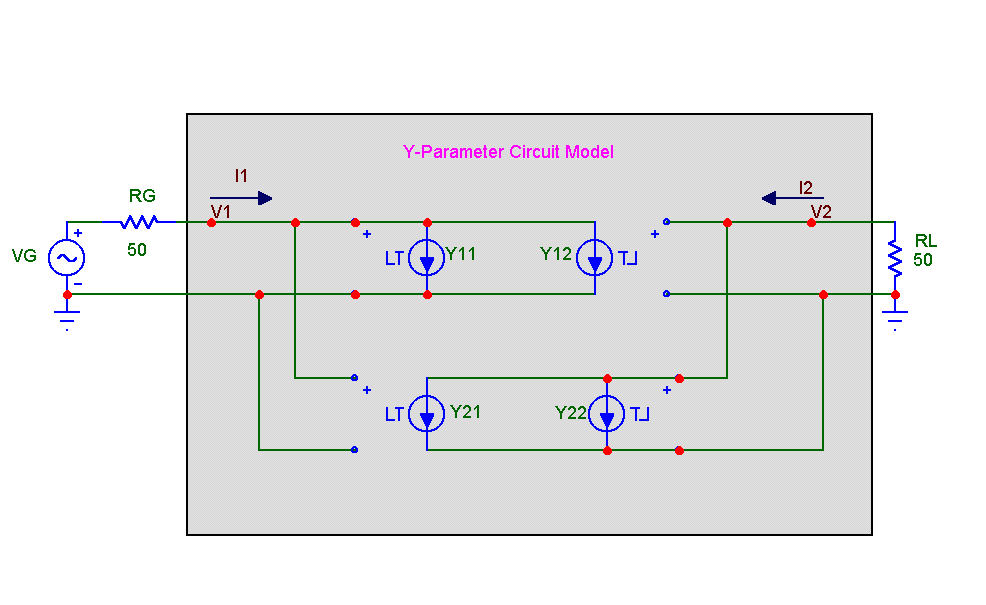
All we need to do is to read in the S-parameters from a file, calculate the equivalent Y-parameter table values at each frequency using the formulas above, and write a file with four tables of values, one each for y11, y12, y21, and y22. The table file is then imported into a circuit like the figure below that implements the Y-parameter equations with Laplace table voltage-controlled current sources.
|

|
This equivalent circuit implements the standard Y-parameter equations:
I1 = y11*V1 + y12*V2
I2 = y21*V1 + y22*V2
where V1 and I1 are the input port voltage and current and V2 and I2 are the output port voltage and current.
While the conversion formulas look simple, they require complex arithmetic. To ease the conversion, we have made a DOS program called STOY(S to Y converter) available for download from our web site at www.spectrum-soft.com.
STOY operation
The program is run with command line arguments that list the input and output file names:
stoy infile > outfile
for example,
stoy GG10V10M.STP > 194.OUT
STOY input file format
The program reads in an ASCII text file containing the S-parameters in standard tabular value
format as follows:
Frequency S11 Mag S11 Ph S12 Mag S12 Ph S21 Mag S21 Ph S22 Mag S22 Ph
where Mag is the magnitude and Ph is the phase in degrees. These can optionally be the real and imaginary parts. A header line of the following form specifies the format.
# [K | M | G | T]Hz S [MA | RI] R[Z0]
K, M, G, or T specify optional frequency units.
S identifies the data as S parameters.
MA specifies the S-parameter data pair format as magnitude, angle, while RI specifies the S-parameter data pair format as real, imaginary.
Z0 specifies the characteristic impedance value.
For example, here is a fragment of the input file for the BFG194 device from Siemens.
! SIEMENS Small Signal Semiconductors
! BFG194
! Si PNP RF Bipolar Junction Transistor in SOT223
! VCE = -10 V IC = -10 mA
! Common Emitter S-Parameters: August 1996
# GHz S MA R 50
! f S11 S21 S12 S22
! GHz MAG ANG MAG ANG MAG ANG MAG ANG
0.010 0.5524 -14.8 24.054 172.0 0.0064 85.3 0.9481 -7.0
0.020 0.5479 -29.1 23.311 165.6 0.0127 78.0 0.9393 -13.9
0.050 0.5716 -66.6 20.450 146.2 0.0290 63.9 0.8185 -31.5
...
4.000 0.8441 67.5 0.535 -44.3 0.3928 -14.3 0.5992 90.5
4.500 0.8478 58.3 0.476 -52.0 0.4157 -25.2 0.6579 73.1
5.000 0.8611 50.1 0.448 -57.6 0.4250 -37.1 0.7108 57.5
5.500 0.8600 42.7 0.427 -63.7 0.4407 -48.6 0.7486 42.1
6.000 0.8579 35.6 0.405 -71.5 0.4307 -61.4 0.7538 28.4
STOY output
STOY generates an output file that contains define statments for each of the four Y sources. The output file typically looks like this:
.define y11
+ (1.000000e+007,-44.567845,10.243495) (1.250000e+007,-44.439330,12.559271) (1.500000e+007,-44.299133,14.804465) (1.750000e+007,-44.148469,16.975683)
...
.define y12
+ (1.000000e+007,-81.407425,-88.961998) (1.250000e+007,-79.433630,-89.671276) (1.500000e+007,-77.825623,-90.140868) (1.750000e+007,-76.468959,-90.474666)
...
.define y21
+ (1.000000e+007,-9.907279,-362.261998) (1.250000e+007,-9.935632,-362.475424) (1.500000e+007,-9.963956,-362.690248) (1.750000e+007,-9.992250,-362.906476)
...
.define y22
+ (1.000000e+007,-66.016592,-699.839215) (1.250000e+007,-66.212254,-692.815564) (1.500000e+007,-66.275002,-685.578696) (1.750000e+007,-66.199028,-678.352899)
...
.define s11
+ (1.000000e+007,-5.154927,-14.800000) (2.000000e+007,-5.225974,-29.100000) (5.000000e+007,-4.858156,-66.600000)
...
.define s21
+ (1.000000e+007,27.623746,172.000000) (2.000000e+007,27.351218,165.600000) (5.000000e+007,26.213866,146.200000)
...
.define s12
+ (1.000000e+007,-43.876401,85.300000) (2.000000e+007,-37.923926,78.000000) (5.000000e+007,-30.752040,63.900000)
...
.define s22
+ (1.000000e+007,-0.462917,-7.000000) (2.000000e+007,-0.543914,-13.900000) (5.000000e+007,-1.739626,-31.500000)
Using the STOY output
When the 194.OUT file generated by STOY is imported into a circuit with a statement like
.import 194.out
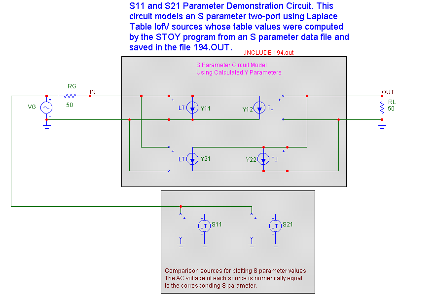
the symbolic variables, y11, y12, y21, and y22 defined by these statements are available for use in the circuit. In the sample circuits to follow we have set the VALUE attribute of each source to one of these four variable names. Definitions of s11, s12, s21, and s22 are also included so that a quick comparison can be made between the measurements of the S-parameters on the Y-equivalent circuit and the original S-Parameters can be compared.
Figure 18 shows how to use the equivalent Y-parameter circuit to model a two-port whose parameters are imported from a file (194.out) generated by the STOY program.
|

|
This is a very general circuit that can model any two-port. You need only change the name of the input file.
Here is a plot of the measured S11 and S21 parameters, together with a comparison plot of the original S11 and S21 parameters.
|
|
Figure 20 shows the equivalent Y-parameter set up to measure the S22 and S12 parameters.
|
|
Figure 21 shows a plot of the measured S22 and S12 parameters, together with a comparison plot of the original S22 and S12 parameters.
|
|
In general, the fit between measured and modeled values is exact at the original data points, whereas logarithmic interpolation used between data points produces some slight discrepancies.
|
|
|
|
|


