|
|
 |
New Christophe Basso SMPS Models
Christophe Basso is writing a new book preliminarily entitled, "Switched-Mode Power Supply SPICE Simulation Cookbook", in which he describes many interesting and useful models, formulas, and circuits that deal with switched-mode power supplies. All of these were crafted by Christophe or translated from earlier models. The models and their demonstration circuits have been ported to MC6 and will soon be a part of the MC6 package. Both the models and some thirty circuits which demonstrate their use are included.
Switched Models: Suitable for transient analysis:
PWMCM: PWM Current Mode Generic Controller
PWMVM: PWM Voltage Mode Generic Controller
PUSH_CM: PWM Current Mode Push-Pull Controller
PUSH_VM: PWM Voltage Mode Push-Pull Controller
HALF_CM: PWM Current Mode Half-Bridge Controller
HALF_VM: PWM Voltage Mode Half-Bridge Controller
FULL_CM: PWM Current Mode Full-Bridge Controller
FULL_VM: PWM Voltage Mode Full-Bridge Controller
2SWITCHCM: PWM Current Mode Two-Switch Controller
DEADTIME: Basso Deadtime Generator
DEADSYNC: Basso Deadtime Synchronizer
DEADDRV: Basso Deadtime
Averaged Models: Suitable for AC analysis (and some transient analysis)
PWMCCM: Generic Converter Operating in CCM
PWMDCM: Generic Converter Operating in DCM
BOOSTDCM: Generic Boost Converter Operating in CCM
BOOSTCCM: Generic Boost Converter Operating in DCM
BUCKCCM: Generic Buck Converter Operating in CCM
BUCKDCM: Generic Buck Converter Operating in DCM
FLYBACKCCM: Ridley Flyback Converter Operating in CCM
FLYBACKDCM: Ridley Flyback Converter Operating in DCM
FWDCCM: Ridley Forward Converter Operating in CCM
FWDDCM: Ridley Forward Converter Operating in DCM
FLYBACKVM: Ben-Yaakov GSIM Flyback Voltage Mode Converter
FLYBACKCM: Ben-Yaakov GSIM Flyback Current Mode Converter
BUCKVM: Ben-Yaakov GSIM Buck Voltage Mode Converter
BUCKCM: Ben-Yaakov GSIM Buck Current Mode Converter
FORWARDVM: Ben-Yaakov GSIM Forward Voltage Mode Converter
FORWARDCM: Ben-Yaakov GSIM Forward Current Mode Converter
BOOSTVM: Ben-Yaakov GSIM Boost Voltage Mode Converter
BOOSTCM: Ben-Yaakov GSIM Boost Current Mode Converter
SEPICVM: Basso Single Ended Primary Inductance Converter (Voltage Mode)
SEPICCM: Basso Single Ended Primary Inductance Converter (Current Mode)
SERPA: Basso Series Parallel Model
SERIPA: Basso Series Parallel Model
Here is the list of sample circuit files that demonstrate averaged (AC) and switched (Transient Analysis) simulations.
Demonstrating Averaged Models:
A_BUCK_CM.CIR
A_BUCK_VM.CIR
A_SEPIC.CIR
A_BOOST_CM_OL.CIR
A_BOOST_CM_ZOUT.CIR
A_BOOST_VM.CIR
A_BUCKBOOST.CIR
A_FLYBACK.CIR
A_FORWARD.CIR
A_RESO_DC.CIR
A_RESO_OL.CIR
Demonstrating Switched Models:
S_FULL_VM.CIR
S_FULL_CM.CIR
S_HALF_VM.CIR
S_HALF_CM.CIR
S_BUCK_CM.CIR
S_PUSH_VM.CIR
S_FLYBACK_CM.CIR
S_BUCKBOOST_CM.CIR
S_FLYBACK_VM.CIR
S_PUSH_CM.CIR
S_BUCK_VM.CIR
S_BOOST_VM.CIR
S_BUCKBOOST_VM.CIR
S_FORWARD_VM.CIR
S_2FLY_CM.CIR
S_BOOST_CM.CIR
S_BUCK_SYN2.CIR
S_BUCK_SYN.CIR
S_FORWARD_CM.CIR
S_FULL_XFMR.CIR
S_HALF_XFMR.CIR
S_2FOR_CM.CIR
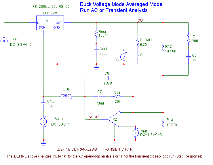
As an example consider the circuit below.
|

|
It is a Ben-Yaakov GSIM buck voltage mode averaged model that is set up so that you can run either AC or transient analysis.
This circuit is set up to test the response of the output voltage to step change in load current in transient analysis and the small-signal open-loop gain in AC analysis. The conditional definition of the CL value opens the loop for AC analysis and closes it for the transient step response.
Here is the open-loop AC analysis showing the output voltage gain and phase:
|
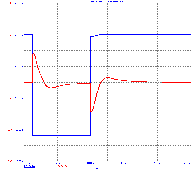
Here is the transient analysis step response.
|

|
The plot shows the response of the output voltage to a step change in the output resistance. The source V10 controls the switch S1, which has an off resistance of 25 ohms, producing a step change in the output current from about 80ma to about 400ma. The output voltage returns to the regulated value within about 1ms.
The interesting thing here is that you can do a transient analysis on a model that is designed to be only an averaged or AC model. Of course you do not see the moment by moment inductor current switching or the output voltage ripple, because these behaviors have been averaged out in the construction of the model.
The model is accurate enough however, to reproduce the large averaged time constants as demonstrated by the damped response to the output load change.
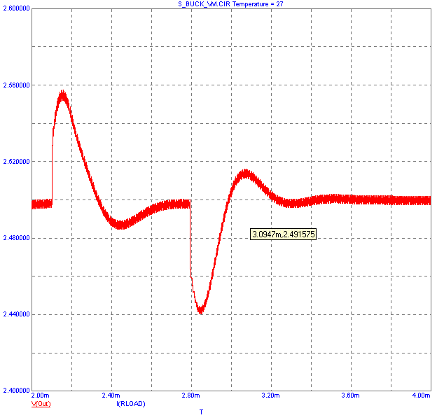
In Figure 10 we show the output of the switched model responding to a similar step change in the output resistance and current. It shows more switching detail, but the overall damped response is about the same.
|

|
The switched model transient analysis required about 400 seconds to complete while the averaged model required about 4 seconds. Shorter run time is a major feature virtue of averaged models.
To complete the review, here is another switched model. This is a simulation of a flyback current mode converter. Here is the schematic. At its heart is the PWMVM voltage mode controller.
|
Here are plots of the output voltage, the clipping current, the leakage current, and the drain-source voltage across the MOSFET switch.
|
|
|
|
|


