|
|
 |
White and Pink Noise Source Macros
*** A user pointed out to us that pink noise sources actually have a -3dB per octave filter rather than the -6dB used in this article and the book the article was derived from. The following technique is still valid, but a different filter must be used to produce the pink noise. We will hopefully have a revised pink noise source available in a coming newsletter. ***
In Micro-Cap, the only components that contribute noise for a noise analysis are resistors, diodes, BJTs, MOSFETs, JFETs, and GaAsFETs. For some components, such as an operational amplifier which has a specified input noise voltage and current, a noise source will need to be added into the schematic to model this appropriately. In order to insert a noise source directly into a schematic, a macro circuit will need to be created to model the source. The following article entails the creation of four macros to model a white noise source and a pink noise source for both current and voltage. These macros are only applicable during a noise analysis.
White Noise Source
White noise has equal energy over frequency. For example, the amplitude of the sound will be the same from 400Hz to 500Hz as it will be from 30100Hz to 30200Hz. White noise is considered a bright noise and is effective in masking other sounds.
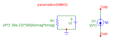
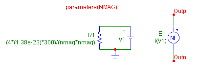
The top circuit below is the white noise current source macro, and the bottom circuit is the white noise voltage source macro. NMAG is the only parameter for each of these macros. It is used to define the magnitude of the noise current or voltage. These macros consist of a resistor, a battery, and a function source. The resistor is used to create a noise current. The noise current that is produced from a resistor is defined by the equation:
I = sqrt(4*K*T / R)
Rearranging this equation to determine the resistance needed to produce the specified noise current, I=NMAG, produces the equation:
R=(4*K*T) / (NMAG*NMAG)
where K is Boltzmann's constant, 1.38e-23, and T is the temperature in Kelvin. In these macros, the temperature has been arbitrarily defined as 300K since that is the default temperature of an analysis. The resistor is connected to a battery that has a value of 0V. The battery is present for two reasons. The first reason is to complete a valid circuit loop with the resistor that the noise current can flow through, and the second reason is that the battery will measure the noise current from the resistor. The battery has been given a 0V value so that it may act as a short and have no effect on the resistor. The combination of the resistor and battery must be isolated from any other circuit elements.
The final element in each macro is the function source. The function source transfers the noise created by the resistor to the desired spot in the circuit and is the output of the macro. The current noise source uses the NFI source and the voltage noise source uses the NFV source. This is the only difference between the two macros. Both of the function sources have been defined as I(V1) to set the value of the sources to the value of the current through the battery which is also the noise current generated by the resistor. The function source has essentially taken the noise current produced from the resistor and has produced an equivalent noise current or noise voltage across its nodes.
|
|
|
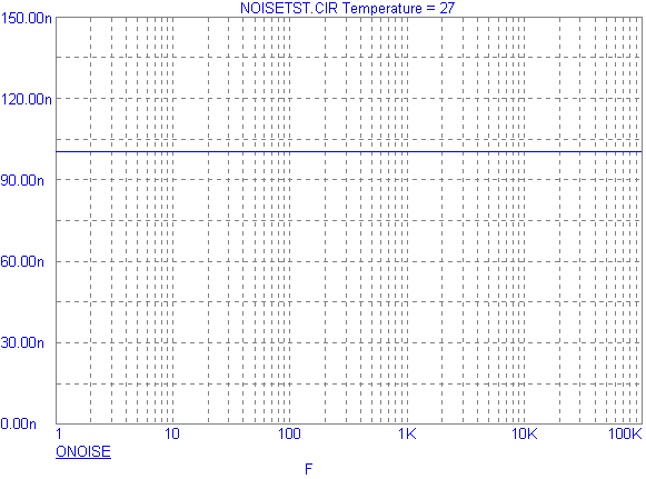
The plot below displays the noise produced by the white noise voltage source during a noise analysis. The parameter NMAG has been defined as 100n in this instance. As can be seen in the plot, a noise of 100nV/sqrt(Hz) is present through the entire frequency range. This is to be expected due to the equal energy over frequency characteristic of white noise.
|
|
Pink Noise Source
Pink noise has equal energy per octave of frequency. For example, the amplitude of the sound will be the same from 100Hz to 200Hz as it is from 200Hz to 400Hz or 10000Hz to 20000Hz. Pink noise has a more natural sound than white noise and is often used as a test signal to tune equalizers or audio spectrum analyzers. Pink noise can be created by low pass filtering or band pass filtering white noise.
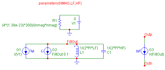
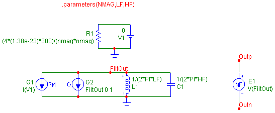
The top circuit below is the pink noise current source, and the bottom circuit below is the pink noise voltage source. The three parameters in these macros are NMAG, LF, and HF. NMAG defines the magnitude of the noise current or voltage at the mid-band magnitude. LF defines the low -3dB frequency of the band pass filter, and HF defines the high -3dB frequency of the band pass filter. These macros consist of the white noise current source in conjunction with a band pass filter. The R1, V1, and G1 components create an exact replica of the white noise current source. The white noise current is filtered through the equivalent of a parallel RLC filter. G2 is a GIofV dependent source and is defined with a VALUE attribute of:
FiltOut 0 1
This source models a 1 ohm noiseless resistor. The input to the dependent source is the voltage at node FiltOut which is also the voltage across itself. The output of the source is a current equal to the voltage at FiltOut. Since I and V are the same, R=V/I calculates to be R=1. The GIofV dependent source needs to be used instead of a resistor because the resistor would add unwanted noise to the macro.
|
|
|
The inductor and the capacitor are then defined so that they will have a reactance of 1 ohm at the specified frequencies, LF and HF, respectively. The inductor has its VALUE attribute defined as:
1/(2*PI*LF)
to set up a -3dB point at the LF frequency, and the capacitor has its VALUE attribute defined as:
1/(2*PI*HF)
to set up a -3dB point at the HF frequency. The only difference between the current and voltage macros is the type of function source used for the output. The current source macro uses the NFI source, and the voltage source macro uses the NFV source. Both function sources have their VALUE attribute defined as V(FiltOut). The function sources are transferring the band pass filtered noise of the resistor to produce an equivalent noise current or noise voltage at the output of the macro.
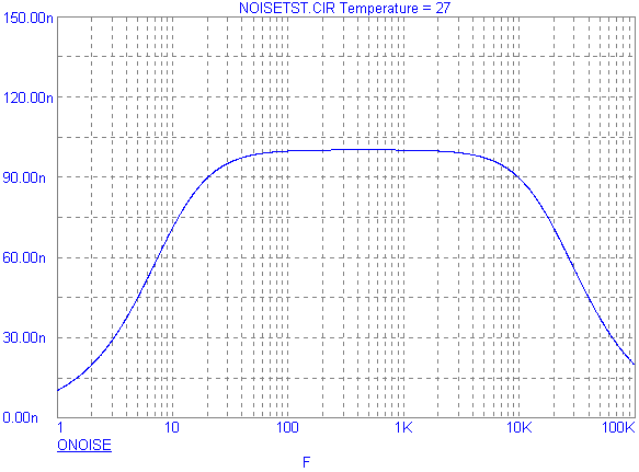
The plot below displays the noise analysis of a pink noise voltage source. The macro was defined with NMAG at 100n, LF at 10Hz, and LH at 20KHz. As can be seen in the plot, the -3dB points occur at approximately 10Hz and 20KHz. The mid band magnitude of the noise is at 100nV/sqrt(Hz).
These pink source macros use band pass filtering of the noise, but in some cases, low pass filtering may need to be used. To change the macro to a low pass filter, delete the inductor from the macro circuit, and eliminate the LF parameter from the .parameters statement. Another method is to define the LF parameter with an extremely small value to essentially act as a low pass filter.
|
|
|
|
|
|


