|
|
 |
AC Analysis Convergence Technique
AC analysis is by definition a small signal, linear analysis. The circuit is linearized for AC simulation through an operating point calculation or by reading in State Variables. In most cases, the operating point calculation will be used. However, a circuit may have trouble converging during the operating point calculation or the user may want to run the AC analysis at a point different than the operating point results. Common types of circuits that may have convergence problems with an operating point calculation are integrators, oscillators, or circuits with multi-stable states. When encountering a convergence error in AC, a simple technique involving the reading in of State Variables can resolve most problems. This technique gathers steady state information from a transient analysis and uses it in linearizing the circuit for AC analysis.
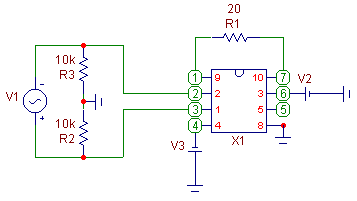
This convergence technique will be demonstrated on the circuit below. The circuit consists of an operational amplifier in a gain configuration. The opamp used is a INA118 precision, low power instrumentation amplifier from Burr-Brown. The input to the opamp is a sine source with 10Kohm resistors to ground at each lead. The opamp is being supplied with +/-15V at its power supplies, and the external gain resistor for the opamp has been defined as 20 ohms. If an AC analysis is run with the Operating Point option in the AC analysis limits enabled and the State Variables option set to Zero, which are the default options, then Micro-Cap will return with the error:
Failed to converge in specified number of iterations at time=0.
This error means that Micro-Cap was unable to converge on a solution during the operating point calculation before the number of iterations specified by ITL1 was reached. ITL1 may be changed by editing its value in the Global Settings under the Options menu while in the schematic editor.
|

|
Upon receiving the error, the steps to achieve convergence for this circuit are as follows:
1) Return to the schematic. The circuit must now be set up so that all sources are only DC. It is possible to replace sources for this portion, such as replacing a sine source with a battery, but note that editing the circuit may change the node number order. The best method is to edit the parameters of the sources. For example, set the F parameter of a sine source to 0, or set the VONE parameter of a pulse source to the value of the VZERO parameter. This will create DC sources out of these components. Any time-based user equation that is used in the circuit must have its time variable changed to 0. There is also no need to change these values back for the AC analysis as they are not used at all for that simulation. In the example circuit, the V1 sine source has its frequency changed to 0.
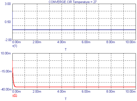
2) Enter transient analysis. In the transient analysis limits, disable the operating point. Set the time range long enough for any initial transients to dissipate. In this case, the time range has been set to 10ms. Run the transient simulation. The results appear below. Notice how the V(5) waveform has settled into its steady state value.
|

|
3) Once the simulation has finished and it is apparent that the simulation has reached its steady state value, enter the State Variables Editor. The State Variables Editor is used to review, edit, or save the values of the state variables for the node voltages, inductor currents, and digital states. For transient analysis, the state variables contain the information from the last data point calculated. The State Variables Editor may be accessed by hitting F12 or by choosing State Variables Editor under the Transient menu. Once in the editor, click on the Write command button. This creates a file on the hard drive with the extension .TOP which contains all of the information from the State Variables Editor. Close the State Variables Editor.
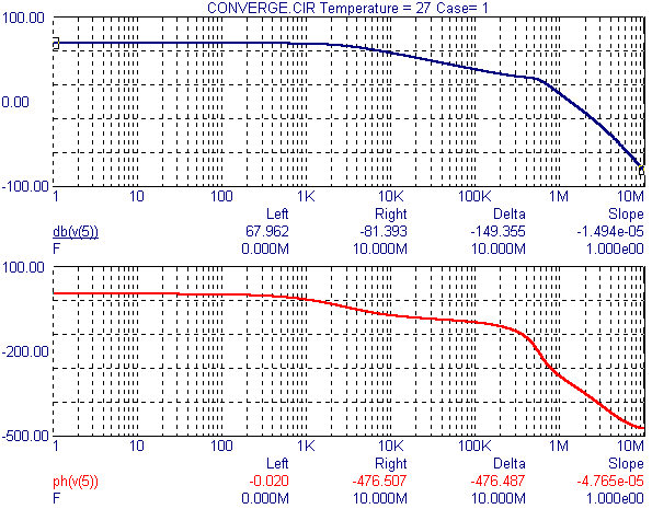
4) Exit transient analysis. Enter AC analysis. In the AC analysis limits, disable the Operating Point option, and set the State Variables option to Read. Run AC analysis. Instead of calculating an operating point, Micro-Cap will look for a file with the same name as the circuit name and the extension .TOP. It will import the data found in this file and linearize the circuit around this data. In this case, the data from the .TOP file is the data derived from the steady state information gathered in the transient analysis. The resulting AC analysis appears below.
|

|
The gain for this opamp is defined by the equation:
1 + 50k/RG
where RG is the value of the gain resistor. With a 20 ohm gain resistor, the gain comes out to be 2501 or 67.962dB. The waveform db(v(5)), which is the output of the opamp, matches exactly with this result at low frequencies as shown in the cursor display above.
This technique is successful because the transient analysis is able to calculate the necessary DC steady state information that the operating point calculation is failing on and supply it to the AC analysis through the Read operation. It can also be used to run an AC simulation on a single circuit in different states such as in saturation or linear operation without the time-consuming step of modifying the circuit. Simply run transient analysis till it reaches the desired state, save the data, and import it into AC analysis for simulation.
|
|
|
|
|


