|
|
 |
Changing the Opamp Model for Different Power Supplies
A typical opamp in circuit design today must be able to function at a variety of power supplies. Some must be able to operate on either a dual or a single rail. The opamp device model in Micro-Cap is capable of handling a wide range of power supplies. However, the opamp model can only have its output range set at one voltage. This means that if you would like to use anything but the standard power supply, usually +/-15 volts, the model may need to be edited.
There are four opamp parameters that control the point at which the opamp saturates: VCC, VEE, VPS, and VNS. VCC is the positive power supply. VEE is the negative power supply. VPS is the maximum positive voltage swing. VNS is the maximum negative voltage swing. The actual power supplies that the opamp uses are those that are connected to its power pins in the schematic. VCC and VEE only define the power supplies that the maximum voltage swings have been set at. Therefore, it is possible to have +/-5 volt power supplies on the schematic but have VCC and VEE set to +/-15 volts. To make the opamp run correctly with +/-5 volt power supplies, VCC, VEE, VPS, and VNS would all need to be changed.
|

|
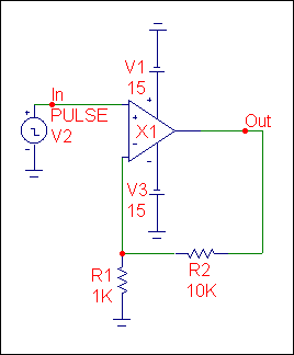
The circuit above has +/-15 volt power supplies in its schematic. The saturation parameters are: VCC=15, VEE=-15, VPS=12, and VNS=-12. What these parameters actually do is determine an offset from the power supply that the opamp will saturate at. It calculates the offset through the following equations:
Positive saturation = VCC - VPS - diode drop
Negative saturation = -VEE + VNS - diode drop
For the circuit above, the positive saturation offset and negative saturation offset will both be approximately 2.4.
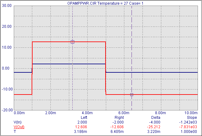
The analysis of the circuit appears in below. A pulse going from -2 volts to 2 volts is input to ensure saturation. As can be seen below, the output of the opamp has saturated at +12.606 volts which corresponds to the offsets of 2.4 volts.
|

|
The power supplies on the circuit are now changed to +/-5 volts. The first figure displays the analysis of this circuit. The opamp now saturates at 2.606 and -2.606. A real opamp with +/-5 volt power supplies would probably saturate at about +/-4 volts. The problem here is that the opamp is still using the 2.4 volt offsets calculated before and now applying it to the +/-5 volt power supplies.
To make the opamp work correctly, the saturation parameters need to be edited. Assuming that we want the opamp to saturate at +/-4 volts, the parameters are changed as follows:
VCC=5
VEE=-5
VPS=3.4
VNS=-3.4
These values produce the desired 1 volt offset. The bottom figure displays the analysis with the edited parameters. The range of the opamp now goes from 4.006 to -4.006. In order to use the opamp model efficiently, these four parameters always need to be checked versus the power supply that is going to be used on the schematic.
|
|
|
|
|


