|
|
 |
Creating and Using a Macro
One of the most useful components provided by Micro-Cap V is the macro. The macro lets you represent a large number of components on a schematic through a single component. This feature lets you black box a portion of the schematic so that it is represented by a simple shape. It is also useful if you have a schematic that is reused often in other circuits. Creating a macro of this schematic makes it as easy to place into another circuit as any primitive component. The macro is very similar to the subcircuit component except that it invokes a schematic whereas the subcircuit invokes a SPICE netlist.
Upon running an analysis, the macro circuit file is substituted for the macro component, so the first step in creating a macro is to create the schematic.
Creating the macro circuit
A new schematic file needs to be opened, and then the schematic may be created either from scratch or through a copy and paste operation. The macro circuit is created just like any other circuit. There are two main differences between a macro circuit and a standard circuit: pin names and parameters.
MC5 needs to be able to link the appropriate nodes in the macro with the external connections in the calling circuit. This is done through placing pin names on the nodes where connections are desired. The pin names are placed by a simple grid text operation. Each pin name must be connected directly to the node or there will not be an electrical connection. Any legal node name may be used for a pin name, but it is best to use a name that provides a description of the pin's behavior.
The second difference is that the macro may use a .PARAMETERS statement that lets you pass parameters to the macro through the calling circuit. The format used for the .PARAMETERS statement is:
.PARAMETERS(par1[,par2[,par3...]])
This is useful in creating a generic template of a component. A specific model would only require new parameters in the calling circuit rather than having to edit the macro circuit. A macro circuit does not require a .PARAMETERS statement.
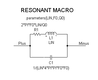
The macro circuit we will use as an example is the two branch parallel resonant network shown in the figure below. The two pin names of this macro are Plus and Minus, and they appear on the two nodes that are to be externally connected. Three parameters are specified to be passed to the macro in the .PARAMETERS statement. These parameters are the inductance value (LIN), the resonant frequency (F0), and the quality factor at resonance (Q0). These three parameters are used to derive the values for the resistance, capacitance, and inductance. The inductance value is taken directly from the parameter LIN, and the resistance and capacitance values are calculated from the following equations:
R = (2*PI*F0*L)/Q0
C = 1/(L*(2*PI*F0)2)
The right sides of these equations are entered as the VALUE attributes for R1 and C1.
|

|
Shape and Component Editors
The next steps are to create a shape for the macro and then to set up the macro as a component. A unique shape was created for the resonant macro in the Shape Editor. The resistor, inductor, and capacitor were copied and pasted from the existing shapes, and then a rectangle was drawn around them. The appropriate leads were then added. The shape doesn't need to be as complicated as this. It may be as simple as a rectangle with two leads, or even an existing shape. The resonant shape may be seen in the test circuit figure.
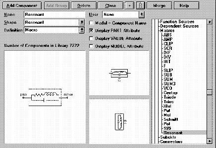
Enter the Component Editor to set up the macro as a component. The Component Editor settings for the Resonant component are shown in the figure below. To add a component, highlight the group that the component will be placed in the hierarchical tree and click on the Add Component command button. In this case, the component was placed in the Macros group of the Analog Primitives.
The Name of the component must be the exact name of the macro circuit. In this case, the name would be Resonant as the macro circuit was called Resonant.cir. The Shape is chosen from the list of shapes available in the Shape Editor, so we chose the shape created earlier, Resonant. The Definition field specifies the electrical definition of the component which in this case will be macro.
The last important step in entering the macro is defining the pins. The pins must match the pin names that were created in the macro circuit. The pins Plus and Minus were added by clicking in the Shape/pin display window and specifying their names and the fact that they are analog pins. The pin marker dot and the pin name may both be dragged to the desired location such as the end of the lead. The other options in the Component Editor, such as positioning the attribute text, mainly define how the component is shown when initially placed in the schematic.
|

|
Testing the Macro
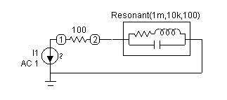
The test circuit we used for the Resonant macro is shown in Figure 14. This is a simple circuit consisting of the macro, a 100 ohm series resistor, and a 1 amp AC independent current source. The VALUE attribute of the macro has been defined as:
Resonant(1m,10k,100)
The name in the VALUE attribute must match the name of the macro circuit, and the number of parameters specified must equal the number of parameters specified in the macro's .PARAMETER statement.
The parameters are passed to the macro in the order that they appear in the .PARAMETERS statement. In this circuit, LIN is defined as 1m, F0 is defined as 10k, and Q0 is defined as 100.
The circuit is set up for an AC analysis run to measure the impedance of the circuit. To do this in MC5, the AC source must be the I independent source that has its value attribute defined as 'AC 1'. This component is found under the Waveform Sources group of the Analog Primitives under the name 'I'. The source must then be placed across the nodes where the impedance is to be measured. The waveform measured is the voltage across the I independent source. In actuality, this gives us the equivalent input impedance of the entire circuit since the current is 1 amp and therefore V is equal to Z.
|

|
The AC analysis is swept over the frequency range of 10Hz to 1MHz. The Frequency Step is set to Fixed Log, and the Number of Points is defined as 251. These two steps need to be done to insure that a data point is calculated at the resonance frequency. If the analysis is set to Auto Frequency Step, the impedance peak we are trying to analyze may not appear if there isn't a data point calculated at that frequency. The figure below shows the results of the AC analysis. At the resonance frequency, the impedance of the macro should be:
Z = R*Q02-j*R*Q0
This equation calculates an impedance value of 6.283k which when added to the 100 ohm series resistor produces the 6.383k value that is displayed at 10kHz in the analysis.
|
|
|
|
|


