|
|
 |
Measuring Power Factor in Linear Circuits
The power factor is the ratio of the real power used in the circuit to the apparent power in the circuit. When a load is completely resistive, the
real power will be equal to the apparent power and the power factor will be 1. When reactances are present in the circuit, some of the energy
will be stored in the circuit and then transferred back to the power source. This inefficiency increases the currents in the system which means
that the apparent power in the circuit must be greater in order to consume the same amount of real power. A completely reactive circuit will consume
no real power and the subsequent power factor will be 0. A low power factor results in greater distribution losses in the power system and should be
avoided. For linear circuits, the power factor is also known as the displacement power factor.
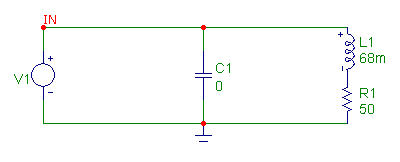
The power factor can be measured in Micro-Cap through the use of the performance functions. The circuit below demonstrates a simple linear load that
consists of an inductor and a resistor. The capacitor initially has its value set to 0 to act like an open circuit and will have its value optimized
later for the power factor correction. A capacitor specified with a value of 0 will be entered into the SPICE matrix as 1e-100 farads which rarely,
if ever, leads to convergence issues. The voltage source models a 120Vrms, 60Hz sine waveform.
|

|
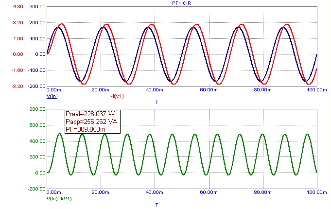
The resulting transient analysis is shown below. The top plot displays the voltage and current of the voltage source. The inductive load has caused
the current to lag behind the voltage. The bottom plot displays the instantaneous power being generated by the voltage source. Note that the current has
been specified as -I(V1) in order to display the current going into the circuit as a positive value. All three of these waveforms need to be plotted as
they will all be used within performance functions in order to calculate the power factor.
The power factor is calculated through the use of performance functions within the analysis text of the bottom plot. The Formula capability within the
analysis text is enabled with the square brackets, [ ], being used as the formula delimiters.
|

|
The real power of the circuit is calculated with the expression:
Preal=[Average(V(In)*(-I(V1)),1,50m,TMAX)] W
The expression between the square brackets calculates the average value of the instantaneous power from a range starting at 50ms to the end of the
simulation. This range will exclude any initial transients. Periodic Steady State in the Transient Analysis Limits can also be used to simulate
without initial transients. The apparent power of the circuit is calculated with the expression:
Papp=[RMS(V(In),1,50m,TMAX)*RMS(-I(V1),1,50m,TMAX)] VA
This expression multiplies the RMS value of the source voltage by the RMS value of the source current. Again, these are calculated starting from 50ms
to the end of the simulation to exclude initial transients. Finally, the power factor is calculated by specifying the ratio of the above two expressions:
PF=[Average(V(In)*-I(V1),1,50m,TMAX)/(RMS(V(In),1,50m,TMAX)*RMS(-I(V1),1,50m,TMAX))]
These formulas return the following analysis text for this simulation:
Preal=228.037 W
Papp=256.262 VA
PF=889.858m
This load requires 256VA of apparent power from the power source in order to receive the 228W of real power that the circuit consumes. This produces a
power factor of approximately .89. For linear circuits, there is a simple technique for improving the power factor. With an inductive load, placing a
capacitor in parallel will correct a lagging power factor by drawing an equal but opposite amount of reactive power. Similarly, for a capacitive load,
adding an inductor to the load would have the same effect.
The C1 capacitor shown in the schematic will be used to compensate for the lagging power factor. In order to determine a value for the capacitor to offset the
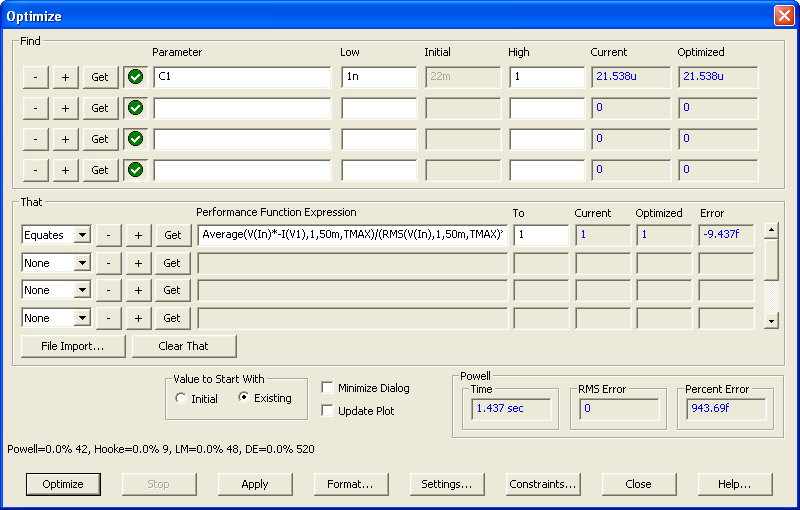
reactive power of the inductive load, the Optimizer in Micro-Cap will be used. In the Transient menu, the Optimize command invokes the Optimizer dialog box
shown below. In the Find section, the C1 component has been defined as the parameter to be optimized. The That section specifies that the capacitor optimization
should try to equate the power factor expression to a value of 1. The power factor expression is the same one from the analysis text formula. Running an
optimization shows that a capacitor with a value of approximately 21.5uF will produce the power factor correction for this circuit.
|

|
In the schematic, the capacitance has been rounded up to 22uF since that is a commonly available capacitor value. Running a transient analysis simulation on
this modified circuit results in the plots shown below. The addition of the capacitor has greatly improved the power factor. The top plot shows that
the voltage and current from the source are now in phase. The analysis text in the bottom plot shows the power factor calculations of:
Preal=228.037 W
Papp=228.051 VA
PF=999.94m
The real power is unchanged from the previous simulation. However, the apparent power has been reduced to the point where it is essentially equivalent to the
real power producing a power factor very close to 1.
|
|
|
|
|


