|
|
 |
VCO with Square Wave Output Macro
A voltage controlled oscillator produces a periodic signal at its output. The frequency of this output
signal is determined by the value of the voltage at the input to the VCO. For most VCOs, the typical
output is a sinusoidal waveform, however, other types of outputs such as a square wave, sawtooth, or
triangle wave output may also be needed. This article describes a VCO macro that produces a square
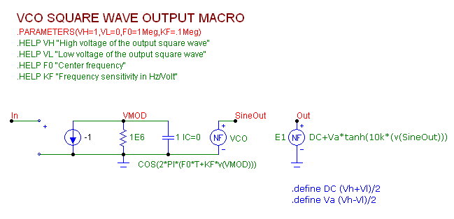
wave at its output. The macro circuit is shown below.
|

|
The square wave VCO macro has four input parameters: VH, VL, F0, and KF. The VH parameter
defines the high voltage value of the output square wave. The VL parameter defines the low voltage
value of the output square wave. The F0 parameter defines the center frequency of the VCO macro
when the input voltage to the macro is 0V. The KF parameter defines the frequency sensitivity to
the input voltage in units of Hz/Volt.
The input of the macro is at node In. The integral of the input voltage is produced at node VMOD
through the use of the IofV source and 1F capacitor. The 1E6 ohm resistor is used as a voltage
limiting resistor in order to keep the output voltage finite. The reason for the integrator is that the
frequency of a sine wave is actually the derivative of the sine argument, so the input voltage needs
to be integrated to properly modulate the frequency. The NFV source at node SineOut produces
a sine wave that has been correctly modulated by the input voltage and the F0 and KF parameters.
The source has been defined with the expression:
COS(2*PI*(F0*T+KF*V(VMOD)))
The waveform at the node SineOut is the traditional VCO sine wave output. Since this macro is to
produce a square wave output, the sine wave needs to be converted into an equivalent square wave.
The E1 NFV source at the output of the macro performs this conversion and is defined with the
expression:
DC+Va*tanh(10k*(v(SineOut)))
The Tanh function is the hyperbolic tangent function whose output is limited between the values of
1 and -1. The argument to the Tanh function is 10k*(V(SineOut)). Since the 10k gain is so high,
the Tanh function quickly transitions between its 1 and -1 limits which converts the sine wave to a
square wave. There are a number of methods that could have been used to convert the sine wave
to a square wave, but the Tanh function was selected as it provides a smooth transition that greatly
aids convergence. The Va and DC parameters are used to scale and shift the output of the Tanh
function so that it will match the values specified for the VH and VL parameters. The DC and Va
parameters have been specified in the following define statements:
.define Va (Vh-Vl)/2
.define DC (Vh+Vl)/2
The output of this VCO macro is then a square wave whose high voltage is set at VH and whose
low voltage is set at VL.
A simple test circuit is setup to test the macro. A Voltage Source is placed at the input of the VCO
macro. The source is defined as a PWL type with the following specification:
PWL 0,1 .2u,1 .7u,4 .9u,4 1u,1 1.2u,1 1.7u,4 1.9u,4 2u,1
This creates a simple pulse waveform from 1V to 4V with a relatively long rise time in order to view
the effects of a changing input voltage on the VCO macro output frequency. The parameters of the
VCO macro are set to:
VH=5
VL=0
F0=10Meg
KF=10Meg
The square wave output of the VCO will go from 0V to 5V. When the input to the macro is 0V, the
square wave output frequency will be 10MHz as specified by the F0 parameter. For each 1V change
in the input voltage, the frequency of the square wave output will change by 10MHz as specified by
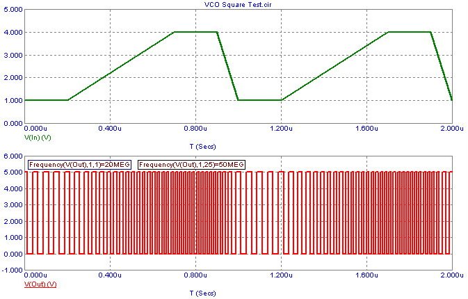
the KF parameter. The resulting transient analysis is shown below.
|

|
The top waveform is the voltage produced by the PWL voltage source at the input of the VCO
macro.
The bottom waveform is the output of the square wave VCO. When the input voltage is at 1V, the
output frequency will be at 20MHz since the frequency is calculated as F0 + Vin*KF. When the
input voltage is at 4V, the output frequency is at 50MHz as expected. Two performance tags have
been placed in the bottom plot to measure the frequency of the waveform at the 1st and 25th instance
of the waveform. The performance tags use the following performance functions:
Frequency(V(Out),1,1)
Frequency(V(Out),1,25)
These two tags confirm the expected frequencies of the output waveform.
|
|
|
|
|


