|
|
 |
Retriggerable Monostable Multivibrator Macro
In the Summer 2006 edition of the Spectrum Software newsletter, a macro circuit was created for a
nonretriggerable monostable multivibrator. In many applications, a retriggerable monostable multivibrator
is useful. The retriggering capability lets the basic pulse duration of the output be extended
when the input is triggered again. For example, if the specified duration of the output pulse is
100ns, when the input is retriggered 75ns after the initial trigger occurs, the output pulse will be extended
for an additional 100ns. In this case, that would produce an output pulse of 175ns. There is
no limit to the number of times that the pulse may be extended. A macro model for a retriggerable
monostable multivibrator appears below.
|

|
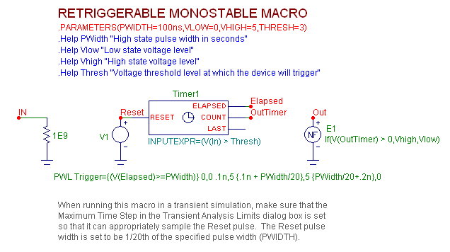
The monostable macro has four input parameters: PWidth, Vlow, Vhigh, and Thresh. The PWidth
parameter defines the length of time in seconds that the output pulse of the multivibrator will
maintain its high state level for before reverting back to the stable low state, and also the amount of
time that the output pulse is extended when it is retriggered. The Vlow parameter defines the voltage
level for the low state output. The Vhigh parameter defines the voltage level for the high state
output. The Thresh parameter defines the voltage level that the input signal will need to exceed in
order to trigger the device.
The input of the macro is located at node IN. A 1G ohm resistor has been placed at this node to
provide a DC path to ground. At the core of the retriggerable monostable multivibrator macro is a
Timer component. The relevant attributes of the Timer component have been defined as follows:
INPUTEXPR = (V(In) > Thresh)
INCREMENT = 1
INITIAL = 0
For the Timer component, the voltage at the Count pin will be set to 0V at the beginning of a simulation
and when the voltage at the Reset pin exceeds 1V. When the INPUTEXPR returns a True
(non-zero) value, the voltage at the Count pin will be incremented by 1V. In this case, the input
expression will become true when the voltage at node In exceeds the specified Thresh level. The
Elapsed output of the Timer is also used in this macro. The Elapsed output tracks the amount of
time since the last true event was triggered in the INPUTEXPR. It produces a voltage value at the
Elapsed output pin equivalent to the number of seconds that have elapsed since the last true input
event.
The reset signal for the timer is created by the V1 voltage source at the Reset pin of the Timer. The
voltage source uses the PWL definition and has its VALUE attribute defined as:
PWL Trigger={(V(Elapsed)>=PWidth)} 0,0 .1n,5 {.1n + PWidth/20},5 {PWidth/20+.2n},0
This source defines a 5V pulse with a width of PWidth/20 seconds. This pulse will reset the voltage
on the Count pin of the Timer back to 0V. The specified pulse will only occur when the expression
defined for the Trigger keyword evaluates to true. The Trigger expression has the following condition
that must be true for the reset pulse to occur.
V(Elapsed)>=PWidth
This condition checks that the voltage at the Elapsed output of the timer is equal to or greater than
the PWidth parameter passed through to the macro. If this condition is true, that means that the
output has been high for the specified pulse width time since the last trigger and needs to return to
its low state.
The output signal of the monostable multivibrator macro is created by the E1 nonlinear function
voltage source. The NFV source has its VALUE attribute defined as:
If(V(OutTimer) > 0,Vhigh,Vlow)
If the voltage at node OutTimer (which is at the Count output of the timer) is greater than 0V, then
the source will produce a voltage of Vhigh volts. Otherwise, a voltage of Vlow volts is produced.
The Vhigh and Vlow values are specified by the parameters the user passes through to the macro.
Essentially, this source produces a pulse of Vhigh volts when the timer has been triggered by its
input expression. Once the timer is reset back to 0V, the pulse will return to its Vlow voltage value.
To demonstrate the basic operation of the retriggerable monostable multivibrator macro, a transient
analysis is run. The input of the macro is connected to two voltage sources in series that have been
defined as:
Pulse 0 5 100n 1n 1n 20n 300n
and
Pulse 0 5 330n 1n 1n 20n 700n
These sources produce a series of 5V pulses that will offset in time in order to test the retriggering
capability of the macro. The monostable macro has its parameters defined as:
PWIDTH=150ns
VLOW=0
VHIGH=5
THRESH=3
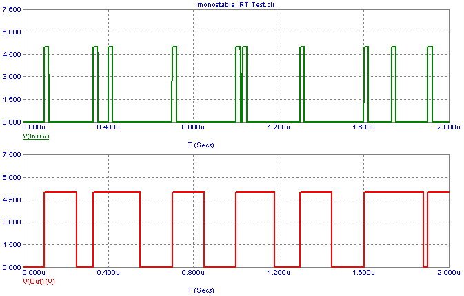
The resulting transient analysis is shown in the figure below. The top plot displays the series of
pulses at the input of the macro. The bottom plot displays the output of the retriggerable monostable
multivibrator. As can be seen in the plot, a single pulse at the input produces a 5V output
pulse of 150ns. When the input is retriggered such as at .4us, the output pulse is extended for an
additional 150ns from the retriggering point.
|

|
Note that when running this macro in a transient simulation, make sure that the Maximum Time
Step in the Transient Analysis Limits dialog box is set so that it can appropriately sample the Reset
pulse. The Reset pulse width is set to be 1/20th of the specified pulse width (PWIDTH). In the
example above, the PWIDTH parameter was set to 150ns. The reset pulse within the macro would
then have a width of 7.5ns. In order to sample this reset pulse adequately, the Maximum Time Step
should be set to a value of 5ns or lower. If the Maximum Time Step is too large, the simulator may
step over the entire width of the reset pulse with the result that the macro is never reset and the
output pulse stays high.
|
|
|
|
|


