|
|
 |
Using the Tolerance Dialog Box
Setting tolerances is typically done in the Attribute dialog box or by directly editing the model in the
schematic file. If many tolerances need to be defined, this can become a tedious process. Micro-Cap
provides the Tolerance dialog box as a means to quickly add, edit, or remove tolerances for any of the
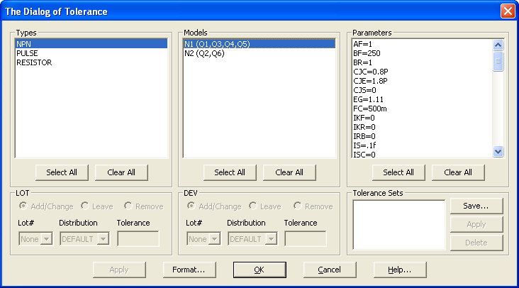
applicable components in the schematic. The dialog box appears as below.
|

|
The Tolerance dialog box, which is accessible from the Monte Carlo dialog box and also from the
Change submenu under the Edit menu, lets you apply tolerances to multiple parameters at once.
You can apply LOT and DEV tolerances to any part that has a model statement. You can also save
Tolerance sets for later use on other models of the same type. The dialog box has these fields:
Types: This list the parts types found in the circuit. You can select one or more types for tolerancing,
although only one type is usually selected.
Models: This lists each model found for the selected part type(s). You can select one or more models
for tolerancing. For resistors, capacitors, and inductors, if the Model attribute has not been specified
in the schematic, the part will still appear in this list but be preceded by a <Blank> designator. If
selected for tolerancing, Micro-Cap will prompt for a model name to assign the selected part(s) along
with the subset of parts from that entry to apply the model to.
Parameters: This lists the model parameters for each selected model. Select the parameters that are to be
toleranced. Use the Ctrl or Shift keys to select multiple parameters.
Lot: This controls the options for the Lot tolerance.
Add/Change: This adds or changes the Lot tolerance of the selected parameter(s) to the value in the Tolerance
field, when the Apply button is clicked.
Leave: This option leaves the Lot tolerances unchanged.
Remove: This option removes the Lot tolerance of the selected parameter(s).
Lot#: This field lets you enter a lot # for the Lot tolerance to provide a means for lot deviations to
track one another.
Distribution: This lets you select the type of distribution. Default means that the model will use the
distribution setting from the Monte Carlo Options dialog box.
Tolerance: This field lets you enter the tolerance. You can enter an absolute tolerance or a percentage
tolerance. For a percentage tolerance, you must specify the % symbol.
Dev: This controls the options for the Dev tolerance. The options are the same as for the Lot tolerance
above.
Tolerance Sets: This lets you assign a name to a tolerance set so it can be used for other parts of the
same model statement type. To name a set, click on Save and enter a name, such as 60n_MOSFET or Caps_5%.
This will save the tolerance settings on the current parameter list so any tolerances must first be applied
to the parameters before saving. To apply a tolerance set to the selected parameters, select the set name
from the list and click on Apply. To delete a tolerance set, select the name of the set to be removed, then
click on the Delete button.
As an example of how the Tolerance dialog box works, the circuit Diffamp.cir will be used. This circuit
is distributed with Micro-Cap. The Tolerance dialog box is invoked through the use of the CTRL+SHIFT+T
hotkey command. The three types of components that have models to tolerance in the Diffamp.cir file are
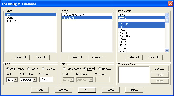
shown in the Types field: NPN, PULSE, and RESISTOR. First, a 10% LOT tolerance will be applied to the BF,
CJC, and CJE parameters of the N2 NPN model. The NPN item is selected in the Types field. Once selected,
all of the available NPN models in the circuit are then displayed in the Models field. The N2 model is
specified in the Models field as:
N2 (Q2, Q6)
which means that the N2 model is being used by the transistors with the part names Q2 and Q6 in the
schematic. Selecting the N2 line in the Models field will then display all of the applicable model
parameters in the Parameters field. Holding the CTRL key down, the BF, CJC, and CJE parameters are
all clicked on in the Parameters field in order to select them. In the Lot section, the Add/Change
option is selected. A value of 10% is entered into the Tolerance field. Since only a Lot tolerance
is going to be added to these parameters, in the Dev section, the Leave option is selected so that no
changes occur to any Dev tolerances. The Tolerance dialog box should now appear as it does below. Clicking
Apply will change the model in the schematic file and update the corresponding parameters in the Parameters
field.
|

|
For the next step, all of the resistors in the schematic will have a 5% Lot tolerance added to them.
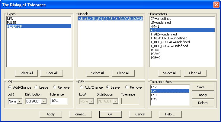
In the Tolerance dialog box, the RESISTOR item is selected in the Types field. In the Models field,
the following line appears:
<blank> (R1,R4,R2,R5,R6,R3,R7,R10,R9,R8)
In the Diffamp.cir file, there are ten resistors, and none of them have a model assigned to them.
However, in order to tolerance a resistor, a model must be assigned to the component. The <blank>
designation allows resistors without models to be selected in this dialog box. Once the above line is
selected, the applicable resistor model parameters are displayed in the Parameters field. In order to
tolerance a resistance, the R model parameter should have the Lot tolerance applied to it so the R
parameter is selected in the Parameters field. Now the same technique used with the NPN model parameters
can be used to tolerance the R parameter. However, the resistor also has four tolerance sets available
to it: E12, E24, E48, E96. The tolerance sets provide predefined tolerance values that can be easily
applied to the selected model. For the resistor, these four sets tolerance the R parameter as follows:
E12 - 10%
E24 - 5%
E48 - 2%
E96 - 1%
In order to set the resistance tolerances to 5%, the E24 entry is selected from the Tolerance Sets list.
The dialog box should appear as it does in below. Next, the Apply button that is within the Tolerance
Sets section is clicked. This applies the 5% tolerance for the R parameter stored in the E24 set to the
selected resistor models.
|

|
Since the resistors that were selected in the Models field did not have any model assigned
to it previously, the Assign Model dialog box shown below will be invoked when the
Apply button is clicked. In the Model Name field, a name needs to be entered. In this
case, the name RMod will be used. The next step is to select which of the resistors that
this model will apply to. Since all of the resistors are to be toleranced, all the entries
in the dialog box are selected, and the OK button is clicked.
At this point, all of the selected resistors will then have their MODEL attribute set to the
specified model name RMod. Also, the following model statement is created in the Models page
of the schematic.
.MODEL RMOD RES (R=1 LOT=5%)
Clicking the OK button in the Tolerance dialog box will then make all the changes permanent.
|
|
|
|
|


