|
|
 |
Using .Warning Statements
The .Warning statements available in Micro-Cap provide a method where the user can create their own set of warning
messages based on circuit criteria that they have specified. This can be useful in flagging instances where the
circuit has exceeded specific design parameters. The general syntax of the statement is:
.WARNING ["Title" [,]] "Message" [,] condition [,print_expr]
This command statement lets you create warning messages that will appear if the condition evaluates to True. The
condition is a boolean expression like PD(R1) > 100m which would be true if the power dissipation of the resistor
R1 was greater than 100mW. If the condition is true at any point during an analysis, the specified message is printed
in both the schematic and the numeric output file along with the value of print_expr if it is specified. If print_expr
is not specified then the analysis sweep variable (T in transient, F in AC, and DCINPUT1 in DC analysis) is printed.
The default title text for each of these messages is "Warning:". If "Title" is specified in the statement, then the
specified title text will be used instead. All warning statements that share the same title text will have their messages
grouped together in the schematic.
All of the commas except the one preceding print_expr may be replaced with spaces. The text "\n" forces a new line in the
message text. This is not needed if the command is entered using the grid text box in the schematic.
Example #1
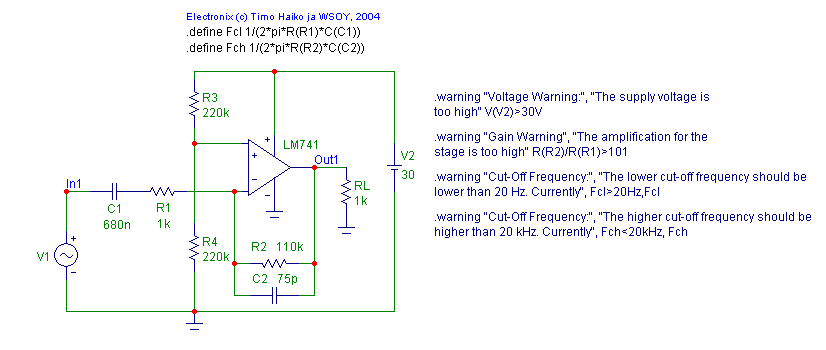
The example below is a schematic of a simple amplifier gain stage.
|

|
Four .Warning statements have been defined for the circuit. The first warning checks the battery voltage, V2, at the positive
power supply of the opamp to make sure it is less than or equal to 30 volts. It is defined as:
.warning "Voltage Warning:", "The supply voltage is too high" V(V2)>30V
The next warning checks the gain of the amplifier stage by returning a warning if the ratio of the R2 and R1 resistors are
greater than 101. It is defined as:
.warning "Gain Warning", "The amplification for the stage is too high" R(R2)/R(R1)>101
The last two warnings check that both the lower and higher cut-off frequencies in the amplifier design meet certain
performance criteria. These warning messages reference the symbolic variables Fcl and Fch which have been set through define
statements in the schematic. The Fcl variable calculates the lower cut-off frequency using the combination of the R1 resistor
and the C1 capacitor. The Fch variable calculates the higher cut-off frequency using the combination of the R2 resistor and
the C2 capacitor. The two warning messages are:
.warning "Cut-Off Frequency:", "The lower cut-off frequency should be lower than 20 Hz. Currently", Fcl>20Hz,Fcl
.warning "Cut-Off Frequency:", "The higher cut-off frequency should be higher than 20 kHz. Currently", Fch<20kHz, Fch
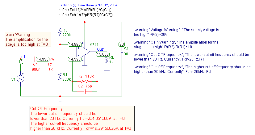
A Dynamic DC analysis is run on the schematic. With the present circuit configuration, the gain warning and the two cut-off
frequency warnings have been triggered. These three warning messages appear in the schematic as shown below.
|

|
When the R2 resistor value is subsequently modified to 100K, the gain and the higher cut-off frequency warning conditions are no
longer violated. The schematic appears as below. Just the lower cut-off frequency warning message is now displayed. Since the
lower cut-off warning specifies the R1 and C1 components, these two components are highlighted in red in the schematic.
|
Example #2
In the previous example, the warning statements had the individual component part names explicitly specified in the condition expression.
Global part names may also be defined through the use of the @ character. All instances in the schematic that match the global part name
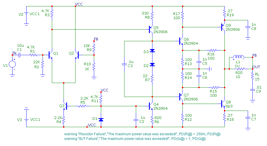
must be valid for the specified condition expression or an error will occur. The schematic below uses two warning statements.
|

|
.warning "Resistor Failure","The maximum power value was exceeded!", PD(R@) > 250m, PD(R@)
.warning "BJT Failure","The maximum power value was exceeded!", PD(Q@) > 1, PD(Q@)
The first statement checks to see if any component whose part name starts with R has its power dissipation exceed 250mW at any point during the
simulation. The second statement is similar except that it checks any component whose part name starts with Q to see if its power dissipation
exceeds 1W at any point during the simulation. In this schematic, all of the transistor part names start with Q, and all of these transistors
use a model statement. If one of these transistors used a subcircuit model instead, the PD operator would not be valid for that component and
an error would be invoked when an analysis was entered.
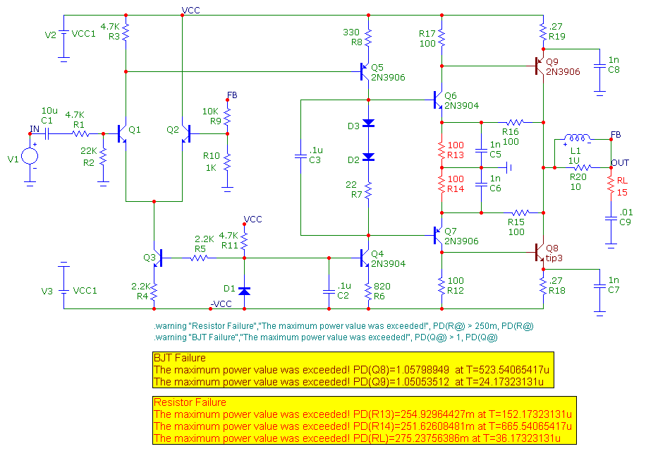
A transient simulation is run for this circuit. At the end of the simulation, the schematic appears as below. The warning messages displayed in
the schematic were also written into the transient numeric output file. During the transient simulation, three resistors (RL, R13, and R14)
and two transistors (Q8 and Q9) exceeded the power dissipation limits set in the warning messages. The warning messages display the excessive
power dissipation values along with the time at which the violation occurred. The message will only display the first violation that occurs
if there are repeat violations.
|

|
The benefit of drawing the referenced components with the color of the warning message text is readily apparent in the schematic. The
resistors and transistors that have triggered the warning messages are easy to pick out within the schematic, and it can really provide
a visual focus on a particular section of the circuit that may need additional work.
|
|
|
|
|


