|
|
 |
Using Multiple Shapes and Shape Groups
Each component within the component library can have multiple shapes assigned to it for use in the
schematic. Whenever a shape is assigned to a component, a corresponding shape group is linked to
the newly assigned shape. A shape group typically contains similar groupings of shapes for multiple
components. In the schematic, the shapes of the components can be changed by editing the SHAPEGROUP
attribute of the component. The advantage of using shape groups in modifying the component in the
schematic is that using the shape group method allows the changing of components en masse. There
are five shape groups that have been created with the standard distributed component library of
Micro-Cap. They are as follows:
Main - This group is the default group for Micro-Cap. Every component has a shape assigned to it
within this group.
DeMorgan - This group contains the DeMorgan equivalent gate symbols for many of the basic digital
primitives.
Electrolytic - This group contains an electrolytic shape for the capacitor component.
Euro - This group contains common European shapes for many of the active and passive devices.
Polarity - This group contains symbols that display the polarity for the capacitor and resistor
components.
An individual component can have any number of Shape Group:Shape pairs assigned to it. For
example, the default settings of the resistor have the following pairs:
Main:Resistor
Euro:Resistor_Euro
Polarity:Respolar
Setting the SHAPEGROUP attribute for a resistor to Euro will cause that specific resistor to use
the Resistor_Euro shape in the schematic.
Assigning multiple shapes to a component
All shapes available within Micro-Cap are created in the Shape Editor which is available under the
Windows menu. At this point in the article, the assumption is that any shapes to be assigned have
already been created in the Shape Editor.
Shapes are assigned to components in the Component Editor which is available under the Windows
menu. When a component is selected in the tree on the right hand side of the Component Editor,
all of its general properties are available for editing. The Shape entry for each component has
two fields. The left field defines the shape group name, and the right field defines the actual
shape. Every component will contain a shape group called Main. Components that use just a single
shape must have that shape assigned within the Main group.
As an example of adding a shape to a component, the Var_resist shape will be assigned to the
Resistor component. The Var_resist shape is a symbol of a variable resistor. The first step in
assigning this shape is to select the Resistor component from the Analog Primitives / Passive
Components section of the component tree. Next, click on the left hand Shape field which will drop
down a list of shape groups that are currently defined for the resistor. At the top of this list
is the entry . Click on this entry, and the following dialog box is invoked.
|

|
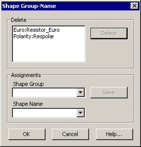
The top section shows the existing Shape Group:Shape pairs for the resistor. Since the Main shape
group must be defined for every component, it is not available in this list. Existing pairs can be
deleted by selecting them in the list and then clicking the Delete button. The bottom section
provides the capability to create new Shape Group:Shape pairs for the selected component.
Shape Group: This field defines the name of the shape group to be assigned. Existing shape groups
can be selected by clicking the drop down arrow to the right of the field. If a new shape group is
to be created, just type in the new name in the field.
Shape Name: This field defines the actual shape to be assigned. Clicking in the field provides
a list of all of the available shapes.
Save: Once a shape group and a shape name have been defined, clicking Save assigns that pair to
the component.
For this example, a new shape group will be created. The name VarComp is typed directly into
the Shape Group field. Then the Shape Name field is clicked and Var_resist is selected from the
list. Clicking the Save button adds this pair into the list in the top section. Click OK to add
this pair to the resistor component. The new shape will now be shown in the Component Editor.
Note that all shapes assigned to a component should have their connections in the same locations.
Moving the pins for one shape will move them for all of the component's shapes, as the pin
locations are constant from one shape to another for a component. Create any new shapes so that
they use the existing pin locations for the component.
Closing the Component Editor and saving when prompted now makes this shape available to use with
any resistor.
A single instance of a resistor in the schematic can be changed to use this shape, or the shape
group VarComp can be given the highest priority in a schematic so that the default shape for the
resistor is Var_resist.
Modifying a single component
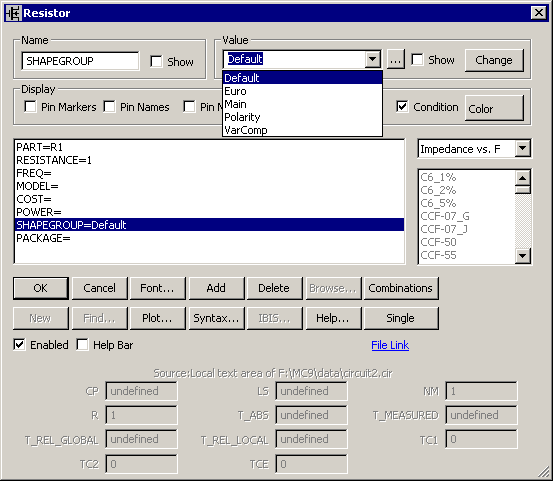
To modify a single instance of the component, simply change the SHAPEGROUP attribute of the device
in the Attribute dialog box. For example, double click on an existing resistor to invoke the
Attribute dialog box. Highlight the SHAPEGROUP attribute in the list. In the Value field in
the upper right hand of the dialog box, click the drop down arrow and a list of available shape
groups will be shown as in the figure below.
|

|
The default SHAPEGROUP attribute value is appropriately enough Default. Default will use the
Shape Group Priority list within the Properties dialog box of the schematic. This feature will
be discussed more in the next section.
When one of the other shape group entries in the list is selected, the resistor will use the
corresponding shape that was defined for that group in the Component Editor.
For our example, if VarComp is defined for the SHAPEGROUP attribute, then that instance of the
resistor will use the Var_resist shape in the schematic. Other instances of the resistor in
that schematic will not be affected by this change.
Changing shape group priority
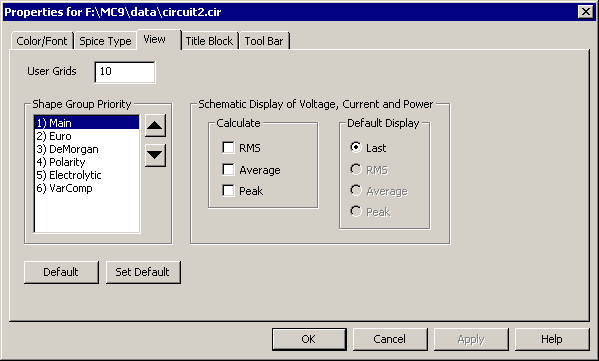
When a component has its SHAPEGROUP attribute defined as Default, it will use the Shape Group
Priority list to determine which shape it will display in the schematic. The Shape Group
Priority list is available under the View tab in the Properties dialog box for the schematic.
The dialog box is displayed below:
|

|
The Shape Group Priority list presents a list of all of the available shape groups. Shape groups
can have their priority changed by selecting the group in the list and then clicking the up arrow
icon to increase the priority or the down arrow icon to decrease the priority. Each component
will start its search at the top of the list. If the component has a shape defined within the
first shape group, then it will use that shape. If it does not have a shape defined within that
group, it will proceed to the second shape group. If it does not have a shape defined within
the second group, it will proceed to the third shape group. It will continue in that manner until
it finds a shape group that it has a shape defined within. Since Main will always have a shape
defined for every component, any shape group below Main in the list will never be accessed. Any
component that has had its SHAPEGROUP attribute modified so it uses a specific shape group will
not be affected by any changes in this dialog box.
Changing the priority in the Properties dialog box will only have an effect on that specific
circuit. To change the shape group priority for new circuits, go to the Options menu and select
Default Properties For New Circuits. Click on the Schematic tab in the upper row and the View
tab in the lower row. The list is available to edit here in the same manner as the standard
Properties dialog box. This will set the default priority whenever a new schematic is
created.
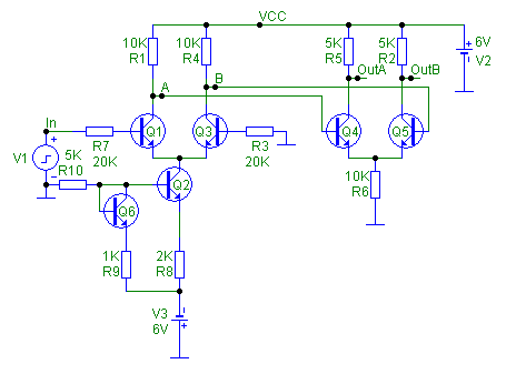
To see how the priority can modify a circuit, load the file Diffamp.cir. Double click in an empty
area of the schematic or hit F10 to invoke the Properties dialog box. Click on the View tab.
Select the Euro shape group and hit the up arrow button until it is listed as having the highest
priority. Click OK. The Diffamp circuit now appears as below.
|

|
Nearly all of the components in this schematic have a shape defined within the Euro shape group.
Since Euro now has the highest priority, these components will use the corresponding European
shapes in the schematic. The Pulse Source is the only component that does not have a shape defined
in the Euro shape group. It continues to use the standard pulse source shape defined in the Main
shape group.
|
|
|
|
|


