|
|
 |
Peak Detector Macro
Peak detector circuits are used within many types of receivers. A simple peak detector is created from a diode and
a parallel resistor-capacitor combination to store the peak voltage. Depending on the RC time constant, this
configuration can encounter significant droop error. A behavioral model of an ideal peak detector can eliminate
this droop error for simulation purposes. The macro circuit below shows one method for creating an ideal peak
detector.
|

|
The peak detector macro has a single parameter passed through to it. The Type parameter defines
whether the detector will store positive peaks or negative peaks. When Type is set to a value of
1, the detector will be a positive peak detector. When Type is set to a value of 2, the detector
will be a negative peak detector.
The macro circuit consists of just two components. The resistor is present to ensure that there
is a DC path to ground at the input of the macro. The Sample and Hold source provides all of the
functionality of the detector. The Sample and Hold source has its attributes defined as follows:
INPUT EXPR = V(In)
SAMPLE EXPR = TypeExp
In the Text page of the macro schematic, the following If statement has been entered to define the
TypeExp variable:
.if Type==2
.define TypeExp V(In) < V(Out)
.else
.define TypeExp V(In) > V(Out)
.endif
If the Type parameter is set to 2, then the first define statement is used to define the TypeExp
variable, otherwise the second define statement is used. Since the SAMPLE EXPR is defined for the
Sample and Hold source, the source will operate in track and hold mode. For the positive peak
detector mode, when the voltage at node In is greater than the voltage at node Out, TypeExp
evaluates to true, and the source will track the voltage at node In. When the voltage at node
In falls below that of node Out, TypeExp evaluates to false, and the source maintains its last
sampled value which will be the highest value of V(In) up to that point of the simulation. The
negative peak detector operates in a similar manner except that it samples the input waveform
when V(In) is less than V(Out), so that it always maintains the lowest value of the input.
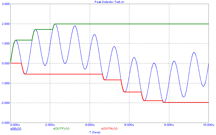
A simple test circuit was created that sums a one volt, 100kHz sine source with a one volt, 1MHz
sine source. This summed waveform is then fed into the input of both a positive peak detector and
a negative peak detector. The resulting transient analysis is shown below.
|

|
The V(In) expression plots the sum of the two sine sources. The V(OutP) expression plots the
output voltage of the positive peak detector, and the V(OutN) expression plots the output voltage
of the negative peak detector. It is a simple procedure, using Cursor mode, to see that the
positive and negative peaks of the input waveform are at 1.988V and -1.988V respectively.
|
|
|
|
|


