|
|
 |
Optimization in Dynamic DC
The optimizer available within Micro-Cap provides a method to systematically modify component parameters to maximize,
minimize, or equate a chosen function of the circuit. The optimizer is available within all analysis modes. In
transient, AC, and DC analysis, performance functions are used as the measurement criteria. In Dynamic DC, since
the analysis calculates just a single data point, circuit variables such as the voltage at a node or the current
through a resistor can be optimized directly. This is very useful for optimizing a circuit to run at a desired bias
point. This article will describe the use of the optimizer in Dynamic DC by optimizing a current in a Widlar current
source circuit.
|

|
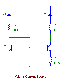
The Widlar current source appears in the figure above. The Widlar current source is used to
maintain a small current in an integrated circuit in the place of a large resistor since it will
occupy a much smaller area of the chip. The two BJTs, Q1 and Q2, are matched transistors. The
approximate current that this source produces at the collector of Q2 is defined by the following
formula:
IC(Q2) = (VT/R3) * ln(IC(Q1)/IC(Q2))
The above equation is nonlinear and requires an iterative process to calculate the value of the
R3 resistor needed to produce the desired collector current at Q2. Rather than going through the
tedious iterative process manually, the optimizer available in Dynamic DC analysis can provide a
quick answer to what resistance value is needed.
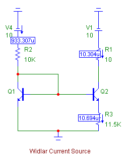
Dynamic DC analysis calculates the DC bias point of the circuit and can display the DC voltage,
current, power, and device conditions on the schematic. The Dynamic DC current calculations for
the Widlar current source using an emitter resistor with a value of 11.5kohms are shown below.
With this emitter resistance, the current source generates a current of 10.3uA.
|

|
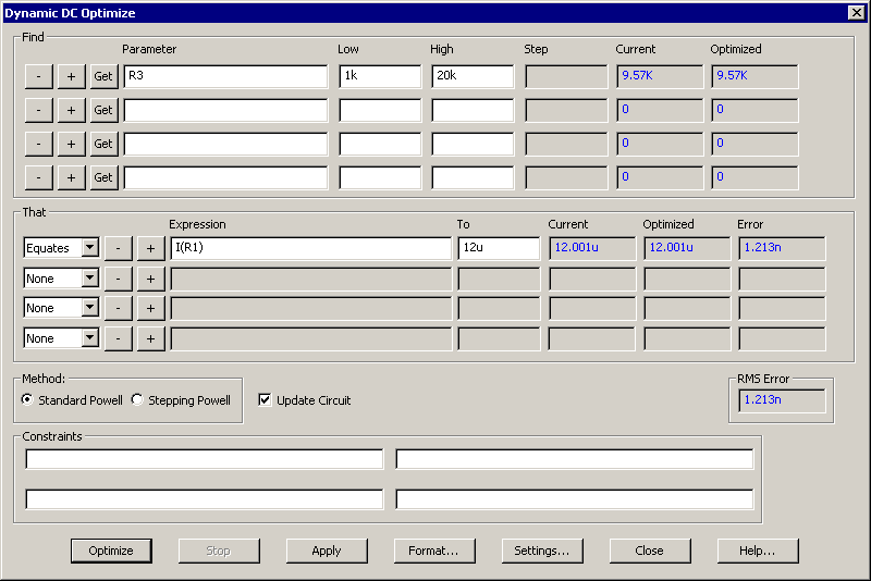
Suppose that the specifications of the circuit require the current source to generate 12uA instead. To calculate the
new emitter resistance, the Optimize command can be invoked from the Dynamic DC menu. The Optimizer dialog box is
displayed below:
|

|
The Find section of the Optimizer dialog box defines the parameters to be optimized. In this case, the resistance
of the R3 resistor will be optimized within the range of 1kohms to 20kohms. The That section defines the optimizing
criteria to use to find the optimal values of the Find parameters. For this example, the single criteria is to have
the current through the R1 resistor, which is equivalent to the collector current in the Q2 transistor, equate to
12uA. In plain English, the optimizer is finding the R3 resistance needed to generate 12uA at the Q2 collector.
Clicking the Optimize button initiates the optimization process. The optimized values will be displayed in the dialog
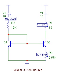
box. If the values look good, clicking the Apply button modifies the circuit with the optimized parameters. To
generate 12uA, the optimizer finds that the Widlar current source needs its emitter resistor set to 9.57kohms. The
schematic below displays the Dynamic DC current calculations with the optimized resistance value.
|

|
|
|
|
|


