|
|
 |
Using the Sample and Hold Source
Sample and hold circuits are typically used in signal processing, event analysis, and analog
to digital conversions among other applications. A sample and hold can be used as an
interface for any device that requires a steady input signal for a specified length of time.
Micro-Cap contains a component called Sample and Hold which is a dependent source that
provides the basic functionality of an ideal sample and hold.
Located in the Analog Primitives / Special Purpose group under the Component menu, the Sample
and Hold can operate in either a time periodic sample and hold mode or a track and hold mode.
There are three attributes that control the operation of the Sample and Hold source: INPUT
EXPR, SAMPLE EXPR, and PERIOD. The INPUT EXPR attribute is the input expression that the
source will be sampling. While this attribute would typically be defined with a node voltage
such as V(Out), the expression may also contain any valid circuit variable. The SAMPLE EXPR
attribute defines a Boolean expression that determines when the input expression should be
sampled. The PERIOD attribute defines a time period at which the input expression should be
sampled. The source works as follows:
If the SAMPLE EXPR attribute is defined, whenever this Boolean expression evaluates to
true (non-zero), the output of the source will be set to the value of the input expression.
When the SAMPLE EXPR attribute evaluates to false, the output of the source will remain
constant at the last value successfully sampled. In this case, the source will operate in
track and hold mode.
If the PERIOD attribute is defined, the source will sample and store the value of the input
expression once every PERIOD seconds. The output of the source will then remain constant
until the next sample. In this case, the source will operate in sample and hold mode.
If both the SAMPLE EXPR attribute and the PERIOD attribute are defined, the SAMPLE EXPR will
have priority, and the source will operate in track and hold mode.
|
|
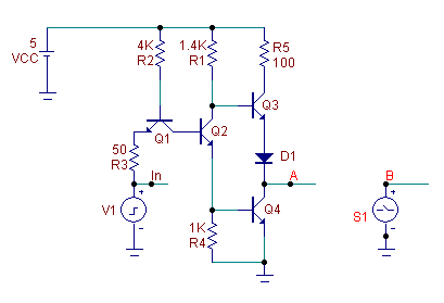
A simple example of the use of the Sample and Hold Source is shown above. The analog
circuitry models a TTL inverter. The input to the inverter is at node In and is defined by
a pulse source that produces a 3.5V, 40ns pulse every 100ns. The output of the inverter is
at node A. The Sample and Hold source, S1, in the schematic produces an output at node B.
For the initial simulation, the attributes of the Sample and Hold source are defined as:
INPUT EXPR = V(A)
SAMPLE EXPR =
PERIOD = 5n
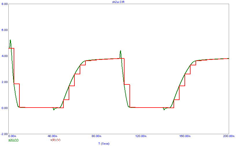
The source will operate in sample and hold mode. It will sample the voltage at node A every
5ns. The resultant transient analysis output is shown below. The transient simulation
has been run for 200ns. The initial sample of the V(A) expression by the source occurs at
T=0. Every 5ns after that, the Sample and Hold source will resample the V(A) expression and
proceed to hold that value for 5ns until the next sampling.
|
|
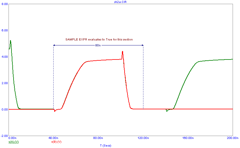
Using the same circuit, the Sample and Hold source will next be defined to work in track and
hold mode by simply defining the SAMPLE EXPR attribute. The attributes for the source are
set to:
INPUT EXPR = V(A)
SAMPLE EXPR = (T Mod 200n > 40n) And (T Mod 200n < 120n)
PERIOD = 5n
Since the SAMPLE EXPR attribute has priority over the PERIOD attribute, the PERIOD attribute
value can remain defined or the user can choose to delete it. The source will operate the
same either way. The Boolean expression that has been defined for the SAMPLE EXPR attribute
in this case will evaluate to true for an 80ns width during each 200ns of simulation time.
The Mod function is a remainder after integer division operator that provides the periodic
functionality for the expression. During each 200ns simulation time window, the expression
will be true when the time value is greater than 40ns and less than 120ns in that 200ns
window. For example, the expression will be true between 40ns and 120ns, 240ns and 320ns,
440ns and 520ns, etc.
The transient simulation of the source in track and hold mode is shown below. While the
SAMPLE EXPR is true (between 40ns and 120ns), the output of the Sample and Hold source
tracks exactly with the V(A) expression that it is sampling. At 120ns, the SAMPLE EXPR
becomes false, and the source will maintain the last valid sample for the rest of the
simulation.
|
|
|
|
|
|


