|
|
 |
Monostable Multivibrator Macro
Also known as a one-shot, the monostable multivibrator is a basic two state device where
only one of the states is stable. When triggered, the output of the monostable multivibrator
will toggle to the unstable state for a specified length of time at which point it will then
return to its stable state until triggered again. This device can be used for numerous
types of applications such as switch debouncing, siren actuation, machine sequencing, pulse
detection or any instance where an output pulse of a fixed time width needs to be produced
from an intermittent input pulse. A macro model for a nonretriggerable monostable
multivibrator appears below. A nonretriggerable type will produce a single timed
pulse output response no matter how many input triggers occur during the specified output
pulse time.
|

|
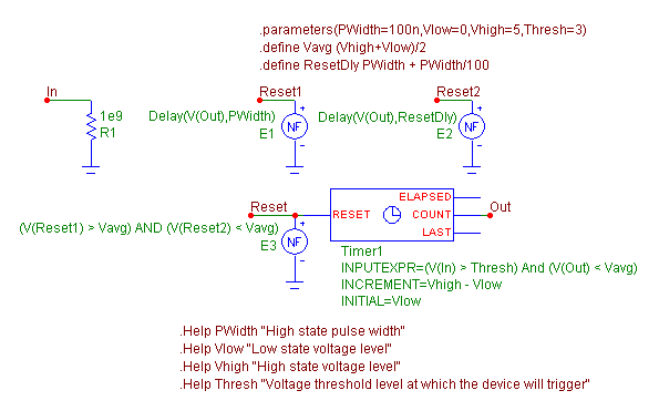
The monostable macro has four input parameters: PWidth, Vlow, Vhigh, and Thresh. The PWidth
parameter defines the length of time in seconds that the output pulse of the multivibrator
will maintain its high state level for before reverting back to the stable low state. The
Vlow parameter defines the voltage level for the low state output. The Vhigh parameter defines
the voltage level for the high state output. The Thresh parameter defines the voltage level
that the input signal will need to exceed in order to trigger the device.
The input of the macro is located at node In. A 1Gohm resistor has been placed at this node
to provide a DC path to ground. At the heart of the monostable multivibrator macro is a
Timer component. The relevant attributes of the Timer component have been defined as
follows:
INPUTEXPR = (V(In) > Thresh) And (V(Out) < Vavg)
INCREMENT = Vhigh - Vlow
INITIAL = Vlow
For the Timer component, the voltage at the Count pin will be set to the INITIAL value at
the beginning of a simulation and when the Reset pin is set to a non-zero value. When the
INPUTEXPR returns a True (non-zero) value, the voltage at the Count pin will be increased by
the INCREMENT value. In this case, the input expression will be true when the voltage at node
In exceeds the specified Thresh level, and the voltage at node Out is below a value of Vavg
which has been defined as follows:
.define Vavg (Vhigh+Vlow)/2
Checking to see if the voltage at Out is less than the average value of the Vhigh and Vlow
parameters ensures that the output is at a low state. This models the nonretriggerable
feature of the multivibrator by masking any low to high input transitions on the input while
the output is in a high state. Since the initial value of the Count pin is set to the Vlow
parameter, whenever the input expression produces a true result, the Count pin will be
incremented by the difference between the Vhigh and Vlow parameters in order to produce the
Vhigh voltage level at the output.
The width of the output pulse is modeled through the use of the three nonlinear function
voltage sources, E1, E2, and E3. The E1 and E2 sources both use the Delay operator to
produce a delayed version of the Timer's Count pin output. These sources have their VALUE
attributes defined respectively as:
Delay(V(Out),PWidth)
Delay(V(Out),ResetDly)
where ResetDly is defined as:
.define ResetDly PWidth + PWidth/100
The output of the E1 source is the Count output waveform but delayed by PWidth seconds.
The output of the E2 source produces the same waveform as the E1 source but time shifted by
an additional PWidth/100 seconds. The E3 NFV source then uses the output of both of these
sources as follows:
(V(Reset1) > Vavg) AND (V(Reset2) < Vavg)
When the output of the E1 source is greater than Vavg and the output of the E2 source is less
than Vavg, the E3 source will produce a value of one volt into the Reset pin of the Timer which
will reset the Count pin back to its Initial value. The reset pulse is how the output of the
multivibrator is set back to the stable low state. The only time the E3 expression will be
true is when the output of the timer has been in a high state for PWidth seconds. At that
point, the high state at the Count output has finally rippled through the delay time of the
E1 source but not through the delay time of the E2 source. The combination of the E1 and E2
sources is used so that the reset pulse will only be active for PWidth/100 seconds, and the
monostable multivibrator will then be ready to receive another input trigger after the reset
pulse is finished. There are a couple of issues to be aware of with the reset pulse. The
first issue is that when the reset pulse to the timer is active, the timer count will not
increment so any input trigger that occurs while the reset pulse is high will be ignored. For
some simulations, the user may need to edit the ResetDly variable so that the reset pulse has
a shorter width so that subsequent input triggers will work. The second issue can occur if
the reset pulse has been set to too small of a value. If the simulation does not calculate a
data point during the time period that the reset pulse will be high then the entire reset
pulse will be skipped and the multivibrator will remain at its high state. Setting the Maximum
Time Step in the Transient Analysis Limits dialog box to a value that would ensure sampling
during the reset pulse would solve this issue. The PWidth/100 value was determined to be a
good trade off between these two issues while allowing for a wide range of output pulse
widths.
A simple example schematic using the monostable multivibrator macro appears below. In this
example, the monostable multivibrator is being used as a switch debouncer in order to supply a
clean clock pulse. Switch bounce can occur because a switch may not switch cleanly and can
have multiple transitions during the time required to open or close. A debouncer will suppress
the additional transitions from passing through to the rest of the circuit.
|

|
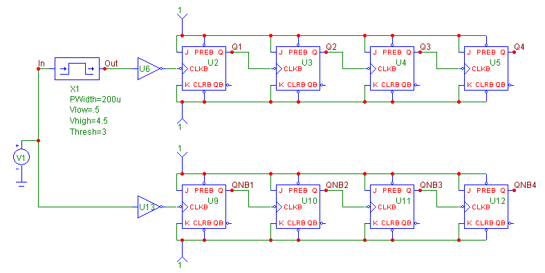
The switch bounce waveform is modeled through the use of the PWL capability within the
Voltage Source component. The PWL capability provides the means to define the X,Y data
points of a waveform and can be very useful when creating unique pulse waveforms. This
source is then fed into the monostable multivibrator macro. The parameters for the macro
have been defined as:
PWidth = 200u
Vlow = .5
Vhigh = 4.5
Thresh = 3
The monostable multivibrator will produce a 4.5 volt, 200us pulse at the output when the
input signal to the macro exceeds 3 volts on a positive going transition. The output of
the multivibrator provides a clean clock pulse to a four bit counter that consist of JK
flip-flops that are setup to count upon each valid transition of the clock input. An
inverter is placed between the macro and the counter so that the macro output will be
converted into the negative going clock transition that the JK flip-flops are looking
for.
A duplicate counter circuit is also present in the schematic. This circuit does not have
the monostable multivibrator macro between the switch bounce waveform and the counter.
This circuit will be used to show the deleterious effect that the switch bounce can have
on the counter circuit if a debouncer is not present. The resultant transient analysis of
this schematic is displayed below.
|

|
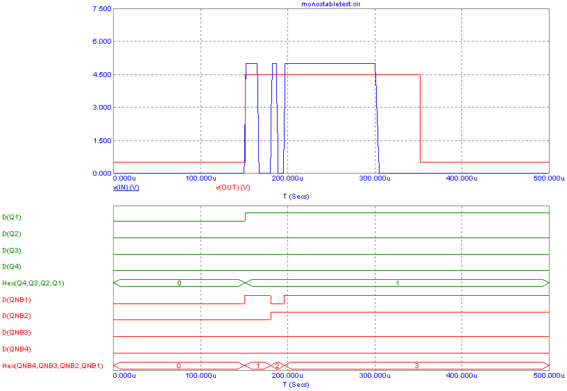
The transient simulation has been run for 500us. The top plot displays the input and output
waveforms for the multivibrator macro. Note how the multiple transitions in the switch
bounce input waveform have been turned into a single pulse at the output of the
multivibrator.
The bottom plot shows the digital output of both of the counter circuits. The D(Q1)
through D(Q4) waveforms display the output of the counter that has had its clock signal
debounced. Only a single count has occurred as the Hex output of this counter has gone
from zero to one. The D(QNB1) through D(QNB4) waveforms display the output of the counter
that has the switch bounce waveform as the clock signal. In this instance, each of the
transitions that occurred in the switch waveform end up causing the counter to increment,
and the Hex output of this counter has gone from zero to three.
|
|
|
|
|


