|
|
 |
Resettable Integrator Macro
The Int macro within Micro-Cap is one of the most useful macros for system modeling. It produces an output
signal which is the integral of the input signal to the macro. With the current Int macro, the output is
the integral of the waveform over the entire period of the simulation. There is no means of resetting the
macro. This article will describe a revised macro circuit that adds a resetting capability to the integrator
macro.
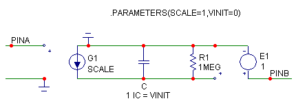
The standard integrator macro that is distributed with Micro-Cap is shown below. Two parameters are
passed to this macro: SCALE and VINIT. The SCALE parameter multiplies the integral by its defined value,
and the VINIT parameter defines an initial value for the integration.
|

|
The operation of the macro is fairly simple and takes advantage of the integrated nature of a capacitive
voltage. The input voltage to the macro is converted by the G1 source into an equivalent current
multiplied by the SCALE parameter. This current is then used to charge a capacitor. Since the value of
the capacitor is 1 Farad, the voltage across it will be the integral of the current though the capacitor.
The VINIT parameter is used to set the initial condition of the capacitor in order to provide an initial
value that the integrated voltage is then built upon. The parallel resistor keeps the voltage finite when
there is a DC voltage input. The E1 source then provides a buffered output which reproduces the integrated
voltage across the capacitor at the output pin.
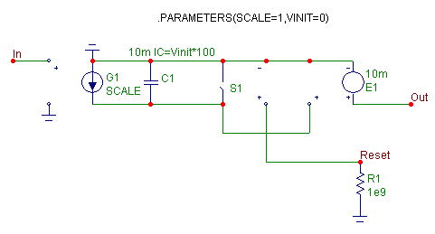
The standard integrator macro will be used as the basis for the resettable integrator macro. The resettable
integrator macro circuit is shown below. It passes the same two parameters, SCALE and VINIT, as the standard
integrator macro. The basic operation of each of the macros is the same.
|

|
The main modification is that the parallel resistor has been replaced by an S (V-Switch) component. The
input of the switch samples the voltage at the Reset pin, and the output of the switch models the parallel
resistance of the integrator. The model statement for the switch is defined as:
.MODEL RPAR VSWITCH (RON=1u ROFF=1Meg VON=.75 VOFF=.25)
When the voltage at the Reset pin is below .25 volts, the switch will be off and the resistance of the switch
will be 1Meg. The macro will then operate in the same manner as the standard integrator macro. When the
voltage at the Reset pin is greater than .75 volts, the switch will be on and the resistance of the switch
will be 1u. Note that the default value of RMIN, which sets the minimum absolute value of a resistance, in
the Global Settings is 1u so this is the smallest the resistance can be without modifying that setting. The
small parallel resistance will cause the capacitor to quickly discharge bringing the output voltage of the
integrator down to zero volts which essentially resets the macro. The VINIT parameter will only set the
value of the integrator at the beginning of the simulation. Any reset operation will use zero volts as the
baseline. The Von and Voff parameters of the switch were assigned these specific values so that a boolean
voltage waveform could be used on the Reset pin.
A 1e9 resistor on the Reset pin provides a DC path to ground for the node. With the addition of this
resistor in the macro, the Reset pin can be left floating in a circuit that calls the macro. When
floating, the Reset pin will be disabled, and the integrator will operate like the standard model.
The value of the capacitor in the macro has been set to 10mF in order to reduce the RC time constant when
discharging the capacitor during the reset operation. Since the value of the capacitor does scale the
voltage across the capacitor by the factor 1/C, the VofV dependent source (E1) at the output of the macro
must also be scaled accordingly to compensate for this factor. Setting the value of E1 to 10m cancels the
effect that the capacitor value has on the integrated waveform. Finally, the initial condition of the
capacitor must also be scaled so that the VINIT parameter will be treated appropriately. The IC keyword
sets the initial voltage across the capacitor at the beginning of the simulation. However, the E1 source
multiplies this initial voltage by 10m when propagating the voltage to the output. Therefore, the VINIT
parameter must be multiplied by 100 when setting the IC value of the capacitor.
Should the time constant for the reset operation be too slow for an application, changing the capacitor
value in the macro will also necessitate changing the E1 value along with the multiplier for the capacitor
IC statement.
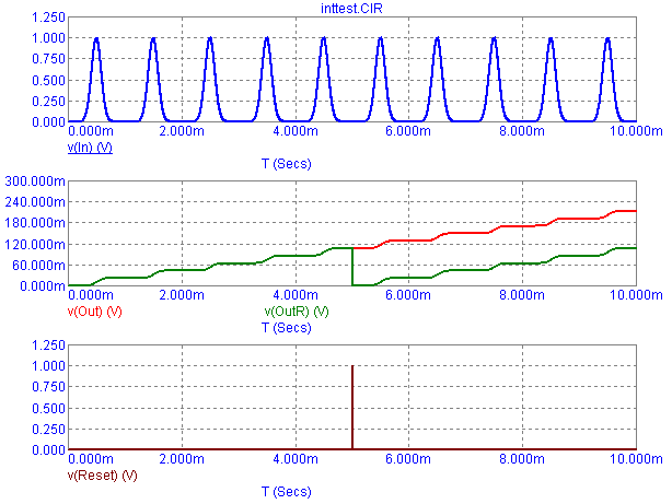
An example circuit has been assembled which contains both the standard integrator macro and the resettable
integrator macro. The two integrators share a common input which is a Voltage Source defined as:
DC 0 AC 1 0 Gaussian 1 500u 200u 1m
which will produce a periodic Gaussian pulse waveform every 1ms. The Reset pin of the resettable
integrator has a pulse source connected to it which will provide a short reset pulse at 5ms.
The resultant transient analysis is displayed below. The top plot is the input waveform. The bottom plot
is the reset waveform. The middle plot contains the output waveforms of both integrators with V(Out)
being the standard integrator output and V(OutR) being the resettable integrator output. The two outputs
match until 5ms when the reset pulse occurs. At this point, the resettable integrator output returns to
zero volts and starts the integration over again.
|

|
|
|
|
|


