|
|
 |
Passing Parameters Through Batch Files
A little known feature in Micro-Cap is the ability to run simulations through a batch process from the
Program Manager command line. Typically this feature is used when multiple circuits need to be run, and
either the numeric output or a printout of the analysis can be used to analyze the finished simulations
after the batch file is done running. The format for running the batch file from the command line is:
MC8 [[/S | /R] | [[/P] | [/PC | /PA]]] [@BATCH.BAT]
Using this format, circuits can be simulated in batch mode by including the circuit name and the
analysis type, /T (transient), /A (AC), or /D (DC) on a line in the text file. The syntax of the
circuit line inside the batch file is:
CIRCUITNAME [[/T /A /D] [/S | /R] [[/P] | [/PC | /PA]]]
The definition for each command line switch is as follows:
/T - Run transient analysis on the circuit.
/A - Run AC analysis on the circuit.
/D - Run DC analysis on the circuit.
/S - Save the analysis to disk for later recall.
/R - Retrieve the analysis run from disk for plotting.
/PC - Print the circuit.
/PA - Print the analysis plot.
/P - Print the circuit and analysis plot.
For example, if the text file TEST.BAT contains the following lines:
PRLC /A /T
DIFFAMP /D /PA
SUBCKT1 /A
and MC8 is invoked through the command line as MC8 @TEST.BAT. The following sequence will occur:
1) Load the circuit PRLC. Run AC analysis. Run transient analysis. Close the circuit file.
2) Load the circuit DIFFAMP. Run DC analysis. Print the resultant analysis plot. Close the circuit file.
3) Load the circuit SUBCKT1. Run AC analysis. Close the circuit file.
4) Exit Micro-Cap.
This works well for running multiple circuits, but consider the case where just a single circuit needs to
be run where one of the parameters will need to be updated for each analysis run. The current batch
process does not have the capability to pass parameters although this will be included in the next
generation of Micro-Cap. For MC8, in order to pass a parameter through to the circuit file that is being
simulated in a batch process, the batch capability of Micro-Cap will have to be combined with the general
batch capability of the Windows operating system.
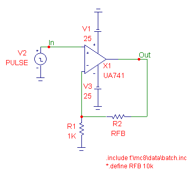
A schematic that has been setup to receive parameters through the combined batch process is displayed
below. The circuit uses the UA741 opamp model in a basic non-inverting amplifier configuration. The
parameter that is to be modified through the batch process must be defined as a variable in the
schematic. In this case, the feedback resistor has been defined with the parameter RFB. Typically, the
RFB parameter would have a corresponding .define statement associated with it such as:
.Define RFB 10k
However, the define statement in the schematic has been commented out, and in its place, the following
include statement has been inserted:
.include f:\mc8\data\batch.inc
The include statement includes text from an external text file in a schematic. For this statement, it will
include a text file called Batch.inc that is located in the F:\MC8\DATA directory. The include file provides
a means to store the define statement for the RFB variable in a file separate from the schematic which can
then be modified through a Windows batch file.
|
|
The first text file created will be the batch file that Micro-Cap runs containing the circuit information.
For this example, the file has been named LIST.BAT. Since only one circuit will be run, it just contains
the following line:
f:\mc8\data\batch1 /a /pa
When the Micro-Cap batch file is run, the circuit Batch1.cir will be loaded, an AC simulation run, and
then the results of the plot sent to the active printer. The second text file will be the batch file
that will run under the Windows operating system. For this example, the file has been named TEST.BAT.
It contains the following lines:
echo .define rfb 1k > f:\mc8\data\batch.inc
f:\mc8\mc8 @list.bat
copy f:\mc8\data\batch1.ano f:\mc8\data\batch1_1k.out
echo .define rfb 2k > f:\mc8\data\batch.inc
f:\mc8\mc8 @list.bat
copy f:\mc8\data\batch1.ano f:\mc8\data\batch1_2k.out
echo .define rfb 5k > f:\mc8\data\batch.inc
f:\mc8\mc8 @list.bat
copy f:\mc8\data\batch1.ano f:\mc8\data\batch1_5k.out
The first line uses the Echo command. This command repeats the string that follows it which in this case
is the define statement for RFB. The redirect expression, >, is used to place the define statement into
the text file Batch.inc. Basically, the include file that the schematic references is being created on
the fly with this command.
The second line starts the Micro-Cap batch process. Micro-Cap will read the LIST.BAT file and run all of
the specified simulations and associated commands. For this example, it runs an AC analysis on Batch1.cir
and then prints the results.
The Batch1.cir has been setup so that the output waveform in the AC analysis is also sent to the numeric
output file. The third line copies the AC numeric output file that was produced from the simulation and
gives it a unique name. Since the Batch1.cir is going to be run a few times during this process, the
numeric output must be saved to a new name after each run in order to be preserved. Otherwise, only the
numeric output from the final run of Batch1.cir would be available.
These three lines are then repeated for the number of times the parameter needs to be changed. Two
modifications need to be made for each set. The define statement value in the Echo line needs to represent
the parameter's value for the next run, and the file name that the numeric output is being copied to needs
to be unique. The TEST.BAT file can be executed by double clicking on the file icon for it in the Windows
explorer.
In the above process, Batch1.cir is being run with the RFB parameter set at 1K, 2K, and 5K. Both the
numeric output from the simulation and hardcopy printouts of the plot will be available to analyze after
the batch process is complete.
In the Micro-Cap batch file, if the /P or /PA switches are being used to produce printouts of the
analysis, there are two points to be aware of when passing a parameter with this method. The first
one is that it is important to set the X and Y ranges in the analysis limits so that it will cover all
the possible ranges of the plots being produced, or the plot may go offscreen and not appear in the
printout. The Auto or AutoAlways options can also be used. The second point is to modify the Plot
Title so the printout displays which parameter value the plot was created with. The Plot Title can be
edited in the Plot page of the Properties dialog box. To edit the title, the Auto checkbox must be
disabled in the Title field. This example used the following entry:
Batch1.cir RFB=$RFB$
where the $RFB$ syntax is replaced with the value of the RFB variable for the run. When RFB is set to
5K, this will produce the plot title:
Batch1.cir RFB=5K
|
|
|
|
|


