|
|
 |
Six Pulse Diode Rectifiers
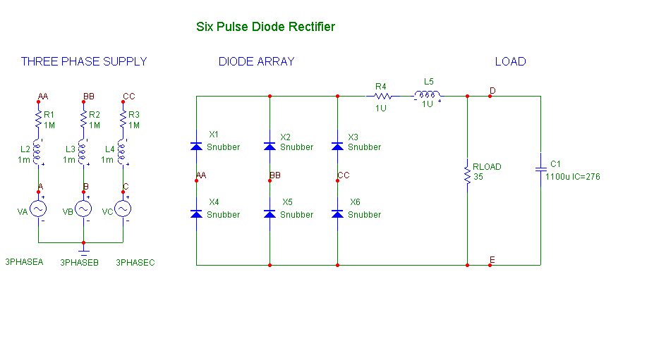
Six-pulse diode rectifiers are often used to produce a constant DC voltage starting with commonly available three phase line voltages. The general circuit is shown below:
|

|
This circuit is described in detail in the following references:
1) Power Electronics, by Mohan, Undeland, and Robbins Pages 103-120
2) Modern Power Electronics, by Andrzej Trzynadlowski, Page 126-129
Here is how to set up the circuit and the accompanying simulation.
First, create the three SINE sources to supply the three phases. Use the following model parameters for the Sine source.
For all sources:
F0 = Frequency = 60
A = Peak Amplitude = 170
All other parameters = 0
For each source
Source 1: PH = Phase added to the Sine argument = 0
Source 2: PH = Phase added to the Sine argument = -120*360/(2*PI) = -2.0944 radians
Source 3: PH = Phase added to the Sine argument = -240*360/(2*PI) = -4.1888 radians
This will produce a balanced set of 3 sine waves of amplitude 170v (120 RMS) and frequency 60 Hz, separated by the requisite 120 degrees.
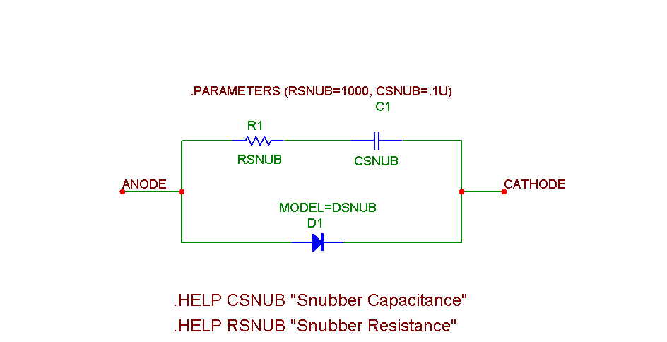
The snubbing diodes are power diodes capable of handling the current and voltage with an energy dissipating R-C filter between the diode's two terminals. These filters provide protection to the circuit by eliminating fast transients and at the same time they frequently make the circuit more convergeable and thus easier to simulate. In this case we use a generic diode with and on resistance of 10m and infinite breakdown. Here is the schematic of the snubbing diode.
|

|
The rectifier has six diodes arranged in two groups. The common cathode group consists of X1, X2, and X3, and the common anode group consists of X4, X5, and X6. One diode from each group is conducting at all times. For example, X1 and X5 fire together whenever the voltage V(A) - V(B) is greater than any other line-to-line voltage. Altogether there are six combinations of diode pairs that fire together to complete the cycle. Each pair fires for 60 degrees or 1/6 of the 16.667ms (60 hZ) period of the sinusoidal inputs.
The approximate average voltage across the output load, V(RLOAD), is found from this formula:
VOUT_AVG = VLLpeak*3/PI - V(X1) -V(X2)
The average DC output works out to about 95% of the peak line to line voltage - two diode drops. In this case:
VOUT_AVG = 294.45*3/PI - 1.03 -1.03 = 279 volts
The ripple is best determined from a transient analysis simulation run.
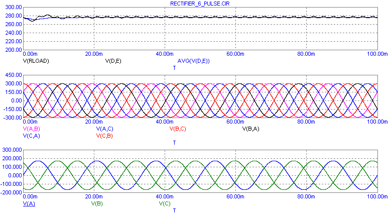
A transient analysis of the circuit is shown in the next figure. The run time is 100msec.
|

|
The average value of the load voltage from this run is actually about 276 volts. The ripple is about 4.2 volts in amplitude or 2.1 volts peak. The plot below shows the harmonic content found in the voltage across RLOAD. The principal components occur at multiples of 360 Hz due to the six-way commutation (6*60Hz).
|
|
|
|
|


