|
|
 |
Phase-Controlled Six-Pulse Rectifiers
Six-pulse diode rectifiers work fine when you want a fixed DC voltage. When a controlled voltage is needed, a thyristor-fired phase-controlled rectifier may be preferred. Here is an example of such a beast.
|

|
In this type of converter the switching is delayed from the moment of natural commutation that would occur in a diode rectifier when the diodes are forward biased. This delay is called the firing angle and it can vary from 0 to 180 degrees. The delay reduces the average output voltage according to the following idealized formula:
VOUT(AVG) = (3/PI)*VPEAK*COS(ANGLE)
Where VPEAK is the maximum or peak value of the line-to-line voltage voltage V(A,B).
Several things are important to note:
• The output voltage can be negative.
• Some firing angles can only be achieved with a suitable EMF voltage to assure SCR bias.
• For firing angles greater than 90 degrees and a negative EMF voltage the rectifier becomes
an inverter and actually provides power to the AC sources.
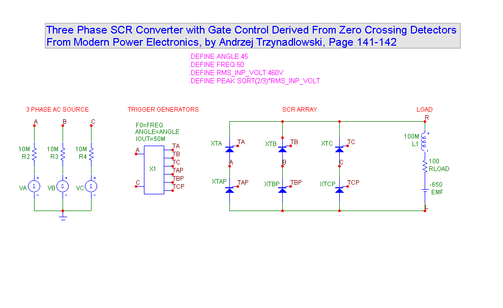
To implement this type of rectifier/inverter from a simulation point of view we need:
• A set of three-phase AC sine sources
• A trigger generator that fires the SCRs
• An array of SCRS
• A suitable load
The first requirement is easily met by three SPICE V sources.
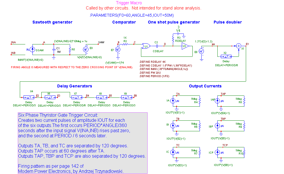
The second requirement is also easily met although with somewhat more work. Here is a macro circuit that does the job.
|

|
The sawtooth generator produces a voltage ramp that takes PERIOD*ANGLE/360 seconds to charge capacitor C1 to 1.0 volts after the input differential voltage V(INA) - V(INB) crosses from a negative to a positive voltage. It does this because current GSAW is set to a suitable IMAX calculated as follows:
IMAX = C * DV/DT = 1m*1.0/(PERIOD*ANGLE/360)
IMAX = .360/(PERIOD*ANGLE) = .360*F0/ANGLE
where F0 is the sine wave frequency and ANGLE is the desired firing angle.
The comparator E7 detects when C1's voltage arrives at 1.0 volts and triggers a one-shot. The one-shot feeds a pulse doubler with produces two pulses with the necessary 60 degree separation. The pulse doubler then feeds a series of delays that create the remaining five trigger signals. Finally each trigger voltage pulse is converted to an output current pulse of magnitude IOUT.
The third requirement is an array of SCRs to control the load. These are arranged as shown and fired according to the pattern detailed on page 142 of the following reference.
Modern Power Electronics, by Andrzej Trzynadlowski
1) XTA and XTBP fire to drive the load towards V(A,B)
2) XTA and XTCP fire to drive the load towards V(A,C)
3) XTB and XTCP fire to drive the load towards V(B,C)
4) XTB and XTAP fire to drive the load towards V(B,A)
5) XTC and XTAP fire to drive the load towards V(C,A)
6) XTC and XTBP fire to drive the load towards V(C,B)
The final requirement is a load, which usually consists of an inductance, a resistance and an EMF load such as a DC motor.
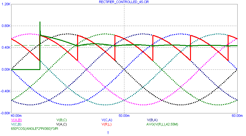
The waveforms for a firing angle of 45 degrees look like this:
|

|
Shown here are the three input signals and their inverses.
V(A,B) V(B,C) V(C,A) V(B,A) V(C,B) V(A,C)
The analysis is run from 0 to 60ms, but only the last 20 ms is shown to avoid the initial transients and show the steady state response.
In this circuit we have set up the following phase angles for the input sources:
VA: 30 degrees
VB: 30 - 120 = -90 degrees
VC: 30 - 2*120 = -210 degrees
With this arrangement, the signal V(A,C) (black plot) is zero at T=0.
Superimposed on these is the output voltage across the load V(R,L) (red plot). Its average value (thick green plot) is also plotted and roughly matches the given formula (thin green line).
VOUT(AVG) = (3/PI)(VPEAK)*COS(ANGLE) -2.0
In this version of the formula we have subtracted a 1.0 volt drop across each of the two SCRs.
The average function should be computed over many intervals or be started at the beginning of a charge cycle for its result to match the above formula.
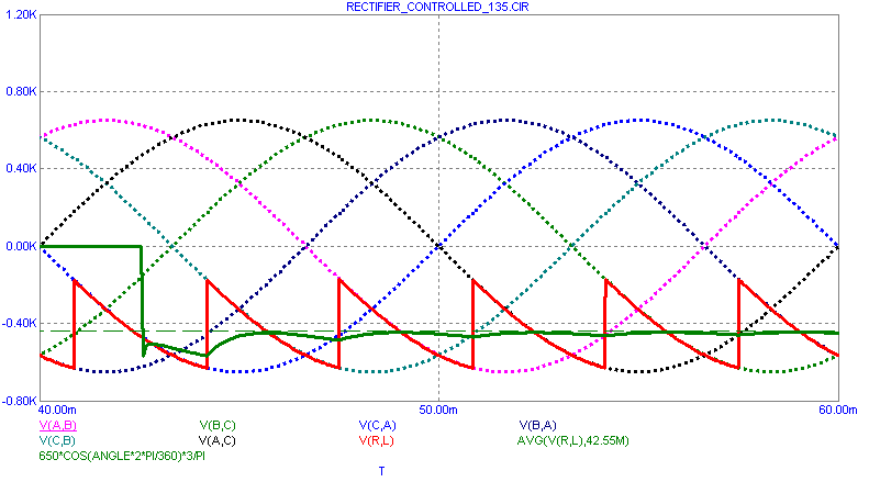
The next figure shows the waveforms for a firing angle of 135 degrees.
|

|
Note that the output voltage is now negative. Since the current can only flow in one direction, the power flow is opposite of the 45 degree case. Power is now flowing from the EMF source to the 3 phase AC source.
The performance plot below shows the average output voltage across the RLE load at the end of the run for angles of 0 to 180 degrees. The plot shows both the theoretical formula and the actual average at the end of the run.
|
|
|
|
|


