|
|
 |
Perfect Transformer vs Ideal Transformer
Questions have arisen about the operation of the transformer component. In some cases, while the voltage gain produced the correct results, the current values of the transformer for the simulation were completely unexpected. The reason for this is that the transformer component, along with its equivalent of two inductors and a K device, operates as a perfect transformer rather than an ideal transformer. The familiar transformer equations for an ideal transformer are (all equations in this article are assumed to have a coupling of 1):
V1 = V2 * n
I1 = I2 / n
Z1 = Z2 * n * n
The equations for the perfect transformer are:
V1 = V2 * n
I1 = I2 * (1 + Z2/(s*L2)) / n
Z1 = Z2 * n * n / (1 + Z2/(s*L2))
As can be seen in the above equations, the value of the secondary inductance can have a significant impact on both the current and impedance transformation ratios while the voltage gain is independent of the secondary inductance.
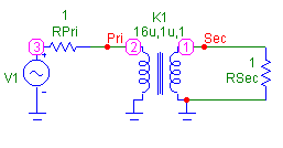
A circuit that demonstrates the effect that the secondary inductance can have appears below. This circuit consists of merely a sine source, two one ohm resistors, and a transformer. The sine source has been defined as a 1kHz, 5V sine wave with the following model statement:
.MODEL INPUT SIN (F=1k A=5)
The transformer has its VALUE attribute defined as:
16u,1u,1
so that it is a 4:1 step down transformer whose primary inductance is 16uH, secondary inductance is 1uH, and coefficient of coupling is 1.
|

|
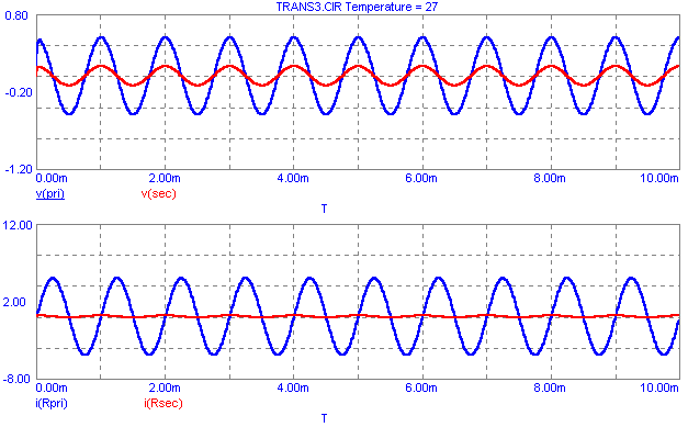
The transient analysis results for this circuit appear below. The circuit has been simulated for 10ms with a maximum time step of 10us. The voltages at the primary and secondary windings appear in the top plot. The voltage gain from the primary to the secondary is the expected .25 but the actual voltage values are lower than an ideal transformer would produce. This is because the impedance reflected back to the primary is lower due to the secondary inductance effect, and this causes a larger voltage drop across the RPri resistor. The primary and secondary currents appear in the bottom plot. The current gain is nowhere near the gain of 4 that would be produced from an ideal transformer because the 1uH secondary inductance is small enough to have a major effect. The current also has a phase shift factored into it due to the reactance of the inductance.
|

|
|
In order to produce the ideal transformer results, the primary and secondary inductances would need to be set high enough where they would have a negligible effect on the current and impedance gains. In this case, setting the transformer inductances to 16H and 1H would have produced values equivalent to an ideal transformer. Dependent sources may also be used to model an ideal transformer.
|
|
|
|
|


