|
|
 |
Digital vs Analog Pullup Resistors
Pullup resistors can be modelled with two components in Micro-Cap. The first component is the basic resistor. This is the analog pullup resistor. The second component is called Pullup in the Digital Primitives. This is the digital equivalent of the pullup resistor. These two parts are not necessarily interchangeable. There is one basic guideline that should be followed when determining which component to use:
Use the digital pullup resistor when a digital output is connected directly to a digital input, and use the analog pullup resistor in any other configuration.
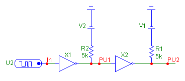
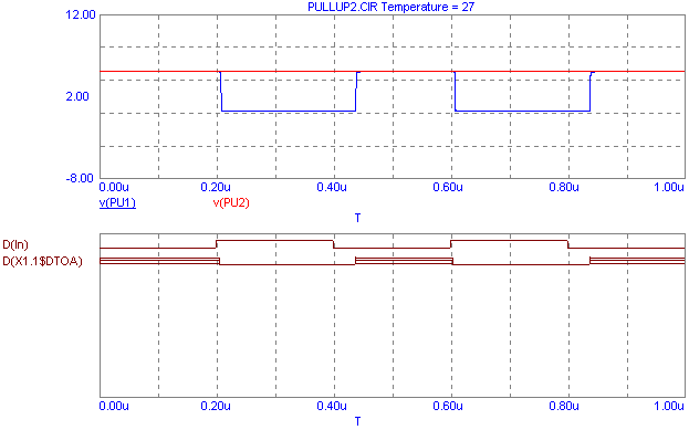
A violation of this guideline appears below. In this case, a 5K ohm resistor, connected to 5V, has been placed at the junction between the output of a 7405 inverter, X1, and the input of a second 7405 inverter, X2. These inverters have open collector outputs, and therefore need a pullup resistor to operate correctly. The problem that occurs is that a single DtoA subcircuit is automatically placed to convert the digital output of X1 for use with the resistor. However, the input of X2 uses the digital state of X1 directly. The digital state of the node has not taken into account the pull up effect of the resistor and is still at high impedance since there is no AtoD component before the X2 input to recalculate it. The high impedance input fails to drive the second inverter which subsequently produces an erroneous output. The analysis below displays the transient results of this circuit. While the V(PU1) waveform is correct, the digital state failed to propagate through the second inverter, and the V(PU2) waveform produces a constant one state. D(X1.1$DTOA) is the digital state at the output of X1.
|

|

|
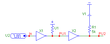
There are three methods to fix this. The first is to place an AtoD model before the input of X2. Another is placing a small resistor in series with the input of X2 which would place an AtoD model in automatically. The third is to substitute a digital pullup in place of the resistor and battery. The circuit below uses a digital pullup between X1 and X2. The pullup's strength is used when determining the digital state of the node and will produce the correct state. The pullup has been defined with the I/O model of IO_PULLUP. In the text area of the circuit is the following model statement:
.MODEL IO_PULLUP UIO (
+ DRVH=5K DRVL=1MEG
+ ATOD1="ATOD_STD" ATOD2="ATOD_STD"
+ ATOD3="ATOD_STD" ATOD4="ATOD_STD"
+ DTOA1="PULLUP_DTOA" DTOA2="PULLUP_DTOA"
+ DTOA3="PULLUP_DTOA" DTOA4="PULLUP_DTOA"
+ DIGPOWER="DIGIFPWR" )
The DRVH and DRVL parameters determine the strength of the component. The DRVH defines the strength at the one state, and the DRVL defines the strength at the zero state. This model statement places the equivalent of a 5K ohm resistor at the node when the digital state is a one. The ATOD_STD subcircuit was chosen for the AtoD parameters because the 7405 uses the IO_STD_OC interface model which also uses that subcircuit. The DIGIFPWR for the DIGPOWER was also chosen for the same reason. The PULLUP_DTOA subcircuit for the DtoA parameters should be used every time a pullup resistor is in the schematic. These subcircuits all reside in the DIGIO.LIB file.
|

|
The analysis below displays the results for the digital pullup circuit which produces the expected results. PU1 must now be plotted with the D operator since it is a purely digital node. Note that the resistor at the output of X2 doesn't need to be changed because there is no digital input directly connected to the node.
|
|
|
|
|


