|
|
 |
Introducing Micro-Cap 6
The next generation of Micro-Cap, Micro-Cap 6, has added many more features and improvements in both the schematic and analysis areas. A preview of some of the features follows. Contact our sales department for upgrade or pricing questions.
Active and Passive Filter Designers
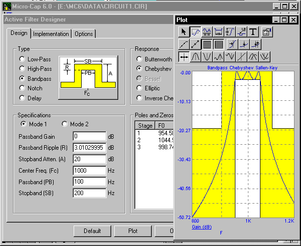
Micro-Cap 6 offers new design features for active and passive filters. The active filter designer supports low pass, high pass, bandpass, notch, and delay filters that can be set up with a Butterworth, Chebyshev, Bessel, Elliptic, or Inverse-Chebyshev response. The possible implementations available are Sallen-Key, MFB, Tow-Thomas, Fleischer-Tow, KHN, Acker-Mossberg, and Tow-Thomas 2. The active filter designer appears below. The passive filter designer supports low pass, high pass, bandpass, and notch filters than can be set up with a Butterworth or Chebyshev response. The two implementations for passive filters are standard and dual.
|
|
The created filter can be sent to a new circuit, to a currently loaded circuit, or can be made into a macro component that is easily accessed through the Component menu. The designer also offers the user the choice of opamps to use for an active filter and can produce the filters with either exact impedance values or standard impedance values.
Exporting PCB Netlists
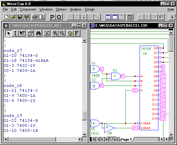
Micro-Cap 6 has the capability to convert schematics into text netlists that can be imported into PCB layout programs. There are four possible PCB layout netlist formats that the schematic can be converted into: Protel 1, Protel 2, Accel, and Orcad PCB II. These netlists can then be imported directly into a PCB layout program that can perform layout and routing on the circuit. This feature saves the problem of having to create the schematic in two separate programs. Simply create the schematic and run the simulation in Micro-Cap, export the schematic to a netlist, and then import that netlist into a PCB program that can accept it.
|
|
Over 10500 of the components in the Component library have at least one package defined for them. The packages can be chosen when the component is placed in the schematic. After placement in the schematic, click on the Package attribute drop down arrow and a list of available packages will be shown. Each of the components has its package pin configuration defined for a package within the Package library.
The Package library is controlled by the Package editor which lets the user add or edit the package information for any of the components within Micro-Cap. The Package editor lets you define basic packages and complex packages. Complex packages are when more than one instance of the component is present within the package. This editor links the pins used in the schematic to the pins that will be used in the PCB netlist.
Sensitivity and Transfer Function Analysis
Two new analyses have been added to Micro-Cap 6. These are the transfer function analysis and sensitivity analysis. These analyses are similar to the .TF and .SENS SPICE commands.
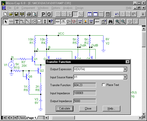
The transfer function analysis calculates the small-signal DC transfer function from a specified input source to a specified output expression. Depending upon the input source and the output expression, the transfer function calculated may be the voltage gain, the current gain, the transconductance, or the transadmittance. To measure the transfer function, Micro-Cap makes a small change in the input source and measures the change in the specified output expression. The ratio of these two changes produces the transfer function. Along with the transfer function, the input impedance at the source, and the output impedance at a specified node voltage expression will be calculated.
|
|
Sensitivity analysis calculates the small-signal DC sensitivity of one or more output expressions to one or more input variables. This analysis determines the DC sensitivity of the specified output expression to any changes in the specified circuit parameters. Sensitivity is defined as:
Change in an output expression / Small change in an input variable
It produces two output values: the absolute sensitivity expressed as a pure ratio and the percentage change sensitivity ratio. Sensitivity analysis is like transfer function analysis, except that it calculates the sensitivity of almost any DC expression to almost any circuit parameter. Circuit parameters for sensitivity analysis include component values, model parameters, and symbolic parameters.
Dynamic DC Analysis
A new schematic operating point display analysis has been added to Micro-Cap 6. In previous versions of Micro-Cap, to see the DC operating point voltages on the schematic, a transient analysis would need to be run with the Operating Point Only check box enabled before returning to the schematic to display the voltages. In Micro-Cap 6, simply enable the Dynamic DC analysis, the operating point will be calculated, and the resulting values will be displayed on the schematic. It is an interactive process in which the user can modify the circuit, the program will calculate the operating point, and then display one or more measures of the DC state on the schematic.
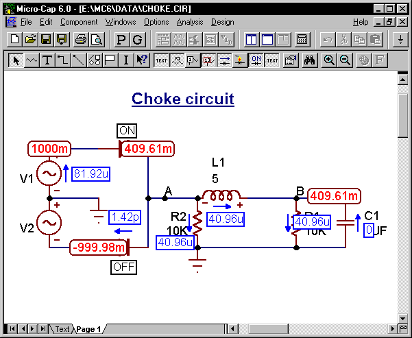
There are now multiple display options available for the schematic. Along with the node voltages and digital states, currents, device power, and device conditions may now also be viewed. The figure below displays a circuit where the voltages (red), currents (blue), and the device conditions (black) are shown. All of these displays will be updated whenever an edit is made to the schematic. All of these displays are also available when returning from transient, AC, or DC analysis in order to view the last calculated data point. These display values may be moved to help clean up the schematic or to place a display in a more visible area.
|
|
The circuit parameters may be edited through the Attribute dialog box in the standard manner. However, the battery, I source, V source, and resistor have an optional slider feature also that can be used to manipulate their values. This slider will appear next to the component and can be dragged on to adjust the value of the component. The up and down arrow cursor keys can also be used to change one of these components.
Enhanced DC Analysis
DC analysis has been enhanced to add even greater capabilities for simulation. There are now more possible input variables that can be swept in a larger variety of ways. The variable 1 input can be swept through an Auto, Linear, Log, or List method. The variable 2 input can be swept through a Linear, Log, or List method. This not only provides greater sweeping capabilities, but it also aids convergence. If one method produces a convergence error, another method may be used to get beyond that error. A new convergence routine was also added to DC analysis so that if a single data point fails to converge, that data point will be skipped and the next data point will be calculated. This lets Micro-Cap display the maximum amount of data that it can produce for the simulation instead of just the data prior to the convergence failure.
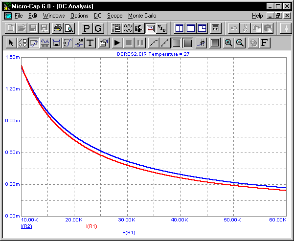
In previous versions of Micro-Cap, DC analysis only allowed a voltage or a current source to be swept. In Micro-Cap 6, the input variables that may be swept consist of the temperature, voltage and current sources, model parameters, and symbolic parameters. For example, a resistor can be easily swept now by sweeping the R parameter in its model statement. The figure below displays the results of a DC analysis when sweeping a resistance.
|
|
Transient, AC, and DC analyses have all added in the capability to step the temperature of an analysis by defining a list of values rather than just a linear progression.
New Macro Capabilities
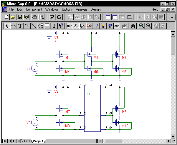
Micro-Cap has added a few new features to its macro capability. Macros may now be automatically created through the Make Macro command. If you want to convert a portion of your schematic into a macro, simply draw a select box around the circuit area and choose the Make Macro command. This command will cut the circuit at all spots where the wire hits the select box and produce pins at each spot. A single component will be created where the select box is. Everything inside the box will be copied to a new circuit and an entry will be made in the Component editor to define the new macro which lets the macro be used in other circuits. The shape of the macro component may have its size and location of the pins adjusted both on the schematic and in the Component editor. This turns the creation of the macro into an easy one-step process. The figure below displays two exact circuits of MOSFET inverters in series. On the bottom circuit, the middle inverter has been converted into a macro through the Make Macro command.
|
|
Macros that have parameters passed to them may now have default values for the parameters defined in the macro circuit. This eliminates the need to always define all of the parameters every time a macro is placed in a schematic.
The extension .MAC is now available for a macro circuit in order to differentiate it from common schematics. Both .CIR and .MAC may still be used for a macro circuit, but .MAC provides an easier recognition of macros for the user.
Multiple Component and Shape Files
Both the Component editor and the Shape editor can now manage multiple files. This gives the user the capability to put their own components and shapes in files separate from the standard ones that come with Micro-Cap. This makes transferring user created components to other people a simple task since only the needed component information can now be passed along.
Updated BSIM3 V3 Model
The latest BSIM3 V3.2 model has been added to the available MOSFET models in Micro-Cap 6. This model is an improved version of the BSIM3 V3.0 model that exists in Micro-Cap 5.
Larger Component Library
Over 12000 components are now available in the Micro-Cap library for simulation. New vendor supplied subcircuits have been added from Harris, Motorola, Analog Devices, Siemens, and others. Microsemi diodes are now available in the Micro-Cap binary libraries.
Improved User Sources and User Files
The format for the user files has been changed to be more compatible with standard output from programs such as Excel. Waveforms may now be saved to any user file after the simulation is finished. The waveforms in the user files can be used by User sources in transient, AC, or DC analysis. The waveforms may also be invoked directly in a plot by plotting them through the new WaveformX and WaveformY operators.
Normalize at Cursor Option
The Normalize at Cursor option is available through the scope features of Micro-Cap. This option will normalize the selected curve at the point that the cursor is situated at.
GMIN Stepping
A new DC operating point convergence routine has been added that will step the GMIN global setting in order to produce a solution. GMIN Stepping will be attempted after both normal methods and Source Stepping have failed to achieve DC convergence.
Monte Carlo Improvements
New tolerance options have been made available for Micro-Cap 6. The capability to tolerance .define parameters now exists and new LOT and DEV extensions allow unique distributions for individual model parameters rather than a single distribution for all parameters.
New Expressions
• IHD function - New IHD() operator computes individual harmonic distortion.
• DSP expressions - DSP math functions such as dB(harm(v(1))) are now possible.
• Bessel Functions - Complex Bessel functions of the first and second kind.
• Complex Series Functions - Complex Series functions. Series(m,1,10,(1+fact(m+2)*(1+J)))
Other New Features:
Analysis Features
• Power Variables - Power variables for plotting generated, stored, and dissipated power in each device and for the total circuit.
• Symbolic Parameters - Stepped symbolic parameters may be used in time range and time step fields.
• Numeric Trackers - Numeric trackers report analysis plot values at cursor, intercept, and mouse positions.
• Data Point Reduction - Reduce data points command now works in both immediate and/or after-run mode.
• X-Y Cursor Bars - Optional Y or X and Y numeric cursor bars.
• Lockable Data Tags - Data tags can be made immobile.
• Analysis Plot Scales - Right-justified scale numeric formats.
Schematic Editor
• Global Nodes - Grid text of the form $G_name connects nodes between main circuit and subcircuits and macros.
• Select Mode Toggle - Spacebar toggles between Select mode and the last used mode.
• Grid Coordinates - Grid coordinates displayed in Shape and Schematic editors and on the waveform plot.
• Recent Files List Size - Set the length of the recently used files list.
• Whole Word Search - Whole word search option in text area.
• Rubberbanding - One direction or any direction rubberbanding option.
Parameter Stepping
• Analysis Stepping - Individual stepping control for AC, DC, and transient analysis.
Probe
• Macro/subckt Plot Selector - Digital component and macro / subcircuit waveform selector list.
• Analysis/properties Control - Analysis Limits and Properties dialog boxes are available within Probe for changing run parameters and controlling the waveform displays.
• Plot/Circuit Top Selector - New controls allow selection of floating display of plot or circuit on top selection.
BJT model
• Substrate diode - Substrate junction capacitor and diode connect between substrate and collector for NPN and PNP, or substrate and base for LPNP and PNP4.
• Lateral PNP model - BJT model statements now handle the alternative LPNP form .model L1 LPNP (model parameters).
• NK parameter - High-current roll-off parameter, default = .5.
• NS parameter - Substrate p-n emission coefficient, default = 1.
• ISS parameter - Substrate p-n saturation current, default = 0.
Resistor model
• New noise parameter - Noise multiplier parameter can be used to eliminate or reduce noise from individual resistors.
Function source model
• New noise expressions - Nonlinear function current sources noise expressions provide user-defined noise formulas.
Sample and Hold model
• Sample Control - New sample expression controls sampling.
Component Library/Editor
• Hidden Pins - Component pins may now be hidden from view on the schematic and automatically connected to a node specified by name.
Miscellaneous
• New Peak Function - Peak performance function that returns the x value at a y peak.
• New Slope Function - New slope performance function.
• Branch Selector - Selector in Go To Performance dialog box allows waveform branch selection.
• Specification Polygon - Polygon object can be used in analysis plots to show design specifications.
• Selected Branch Color - Optional selected waveform branch color.
• Cut and Paste - Copy and paste calculator results to other fields.
• Analysis Type Variable - Analysis type variable for use in range fields.
• Message Delay - User-set time delay for warning messages.
• User Text in Plots - User defined title headers for plots.
• Time and Date Stamps - Simulation Time and Date in output file.
• User Definitions File Variables - Model parameters and symbolic parameters from the User Definitions file are now steppable.
• Colored waveform Branches - Optional different colors for stepped waveform branches.
• Rubberband Hotkey - Hotkey and icon for toggling rubberband mode.
• Improved Find Control Keys - New command hotkeys. CTRL + F to invoke and F3 to repeat.
• Attribute Dialog Box - Model names list tracks typed model name.
• Paste Offset - Offset to repeated paste operations avoids overlap.
• Scale Display - Use of #### numeric format in small windows.
|
|
|
|
|


