|
|
 |
Using a Vendor Supplied Subcircuit
Many vendors now produce SPICE models of their components. Thousands of these SPICE models are available for downloading from the Internet from companies such as National, Motorola, TI, Siemens, and many more. A list of some of these companies may be found on our web site at:
http://www.spectrum-soft.com/links.shtm
While most of these models are included in the latest version of Micro-Cap, there will be a few that will need to be added by the user if they are to be used in a simulation. SPICE models can come in two different formats: .SUBCKT and .MODEL. Almost all vendor supplied models are in the .SUBCKT form. This article describes the process of adding one of these subcircuit models into Micro-Cap's component library.
The Subcircuit Model
For this example, the component to be added will be the AD8011 opamp from Analog Devices. This opamp is a 300MHz, 1mA current feedback amplifier. Analog Device's SPICE models may be found on their web site at:
http://www.analog.com
The AD8011 model was downloaded from their web site and saved in a file called AD8011.MOD. This file contains just the AD8011 subcircuit model, but any number of models may be saved in a single file. The AD8011.MOD file should be copied into the DATA subdirectory. This file may be opened in any text editor or in Micro-Cap itself. There are four items that need to be noted in the file before it can be added to Micro-Cap. All of these items appear in the block of text below.
			* Node assignments
			*                non-inverting input
			*                | inverting input
			*                | | positive supply
			*                | | |  negative supply
			*                | | |  |  output
			*                | | |  |  |
			.SUBCKT AD8011an 1 2 99 50 28
The last line describes three important aspects of the model. The keyword .SUBCKT defines the type of model. In this case, it states that this is a subcircuit model rather than a simple .MODEL. .MODEL statements may appear within a .SUBCKT model, but those statements aren't relevant for importing the model into Micro-Cap. The name of the subcircuit comes next which in this case is 'AD8011an'. Finally, the text string '1 2 99 50 28' defines the pin numbers of the input and output nodes of the model. The first seven lines are comments which are denoted by having the asterisk as the first character of the line. These lines describe the node assignments for the subcircuit pins, which appear on the .SUBCKT line, as follows:
1 - non-inverting input
2 - inverting input
99 - positive supply
50 - negative supply
28 - output
Both the pin number (or pin name) and its assignment need to be known before adding the part to the component library. The file may be closed once the type of model, the name of the model, the pin numbers (or pin names), and the pin assignments are known.
The Shape Editor
The next step in adding a subcircuit model to Micro-Cap is to create a new shape or choose an existing shape for the component. The Shape Editor can be found under the Windows menu. This editor controls the shape library for Micro-Cap. There are currently about 800 shapes available within the shape library. Any of these existing shapes may be used when a model is added to the component library.
In this case, the AD8100 model is a five pin operational amplifier device. Upon scrolling through the list of shapes available in the Shape Editor, the Opamp5 shape is found to be a good match for such a device. Once a shape is found that fits the part, the Shape Editor can be closed without performing any actions in it. However, if an appropriate shape is not found, then one will need to be created in the Shape Editor. This would be done by clicking on the Add command button, defining a shape name, and then using the shape elements to create the shape.
The Component Editor
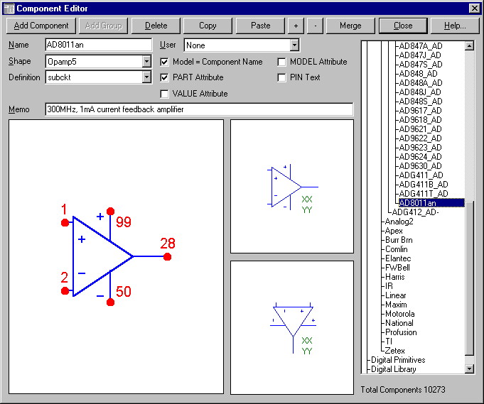
After closing the Shape Editor, the next step is to enter the component information into the Component Editor. The Component Editor can also be found under the Windows menu, and it controls the component library for Micro-Cap. The settings for the AD8011 model appear in the figure below.
|

|
On the right hand side of the Component Editor is the Component selector. This hierarchical list controls the order of the components in the Component menu of the Schematic Editor. The model may be added into any of the available groups or into a group created by the user. To navigate through the list, double click on the group names to toggle them open or closed. Highlight the desired group name and then click on the Add Component command button. This will place a new entry into the list that will be edited to create the AD8011. In this case, the group chosen for the AD8011 was the Analog Library / Vendor / Analog1 / AD847_AD- group.
The Name field should be defined as 'AD8011an'. This is the name of the subcircuit as it appears on the .SUBCKT line in the AD8011.MOD file. For ease of use, the Name field and the subcircuit name should match exactly, but that is not a requirement for the Component Editor. Click in the field for Shape and choose the shape 'Opamp5' from the list. This list of shapes is managed by the Shape Editor. Click in the field for Definition and choose the definition 'subckt' from the list. This defines the component as one that uses a subcircuit model to obtain its electrical characteristics. Since the Name field matches the name of the subcircuit exactly, enable the Model=Component Name checkbox. This stops the Attribute dialog box from opening when the component is placed in a schematic and makes it a one step process for adding the part to a schematic. The Memo field contains a text description of the component and is optional.
The pin names are defined in the lower left hand window. Click in this window to invoke the Pin Name dialog box which defines the pin name and its type. For example, click on the non-inverting input lead, define the pin name as '1', and make sure it is an analog type. Hit OK. Then click on the inverting input lead, define the pin name as '2', and hit OK. Repeat this procedure for the other three pins. After placement, the pin may be moved by dragging on the pin dot, and the pin name may be moved by dragging on the name.
The two windows in the middle of the Component Editor control the initial placement of the attribute text in the schematic. The text location is specified by dragging the generic text block to the desired location relative to the shape in the two basic orientations. Hit the Close command button and then save the changes.
The NOM.LIB File
The NOM.LIB file is stored in the DATA subdirectory. This file is a text file that stores a list of all of the libraries that Micro-Cap will automatically access. Open this file in Micro-Cap. On a new line in this file, add in the statement:
.lib "AD8011.MOD"
If you choose not to keep the AD8011.MOD file in the DATA subdirectory, then a path would also have to be specified, such as:
.lib "C:\MYLIBS\AD8011.MOD"
This statement would reference the file in the MYLIBS directory on the C: drive. Micro-Cap will now be able to find the AD8011 subcircuit model for any schematic.
The Schematic Editor
The final step is using the AD8011 component in a schematic. The AD8011 will appear in the Component menu in the same group that it was added into in the Component Editor. Click on the Component menu and then on the following sequence within the menu: Analog Library, Vendor, Analog1, AD847_AD-, AD8011an. Once the component is selected from the Component menu, it can be placed in the schematic and is available for immediate simulation. The only requirement for this part is that the NAME attribute must match exactly with the subcircuit name. In this case, that would be 'AD8011an' which is its default NAME attribute due to the settings in the Component Editor.
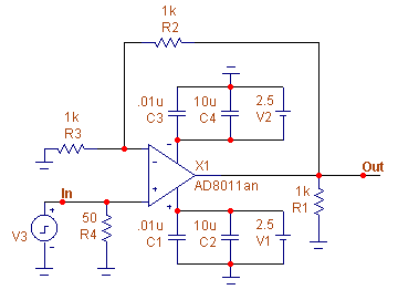
The first figure below displays a test circuit for the AD8011 opamp. This test circuit uses the AD8011 opamp in a simple gain of two configuration. The opamp is running at +/- 5V.
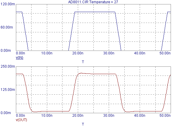
The second figure below displays the transient analysis results of the test circuit. The input to the opamp is a 100mV, 15ns pulse with a 50% duty cycle. Both the input and the output waveforms are being plotted over a time range of 50ns.
|

|

|
|
|
|
|


