|
|
 |
Lossy Transmission Line Modeling
MC5 uses the SPICE3 lossy transmission line model. This model can easily simulate RLC transmission lines if the R, L, and C parameters are known. However, transmission line information often appears only with nominal impedance, velocity of propagation, and attenuation at different frequencies. It is possible to create a subcircuit model using these parameters that will vary the attenuation of the transmission line according to a frequency parameter that is set by the user. This model is only applicable in transient analysis, as it is only valid for one frequency in AC analysis due to the fact that the resistance in the model is based on a fixed, user defined frequency. The following table displays the specifications for an RG6A/U cable type.
|
| RG6A/U Specifications |
Attenuation (dB/100ft) frequency, MHz |
| RG cable type |
Velocity of Prop.,% |
Nominal impedance ohms |
10 |
50 |
100 |
200 |
400 |
1000 |
3000 |
| 6A/U |
66.0 |
75.0 |
0.80 |
1.40 |
2.90 |
4.30 |
6.40 |
11.00 |
---- |
| |
The equations below convert the RG6A/U specifications into the appropriate R, L, and C parameters.
C = 1/(V * Zo)
L = Zo*Zo * C
R = atten * 2 * Zo
where V is the velocity of propagation, Zo is the nominal impedance, and atten is the attenuation at a fixed frequency. The atten value from the specification table needs to be divided by 8.686 to convert it into the needed units of nepers/ft. The value for the speed of light used in this instance is 9.82E8 ft/s. The subcircuit produced is shown below:
* RG-6A/U cable type: 75ohms, 66% velocity of propogation
* default 2.9dB/100ft @ 100MHz
.subckt RG6AU AP AN BP BN
+ params: freq=100MEG length=1
+ atten={table(freq, 10Meg,.008, 50Meg,.014, 100Meg,.029,
+ 200Meg,.043, 400Meg,.064, 1G,.11)}
T1 AP AN BP BN RG6A
.model RG6A TRN (len={length} r={(atten/8.686)*2*75}
+ c=20.6p l=115.6n)
.ends
The subcircuit model consists of a single lossy transmission line model. This subcircuit has two parameters: freq and length. The default frequency is 100MHz and the default length is 1 foot. The length value is used directly in the lossy transmission line's len parameter. The freq parameter is filtered through a table operator that contains data pairs of frequency versus attenuation. The table operator looks at the input, in this case the freq parameter, and will find the corresponding output from the data pairs. Information between specified data points will be interpolated. Note that the output values in the table statement are the attenuation values divided by 100 so that it will correspond to a length value of 1 foot. The value produced by the table operator is used to calculate the resistance of the transmission line. Note that the resistance is being divided by 8.686 in the model to produce the appropriate units of nepers/ft.
|

|
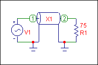
The test circuit for the lossy transmission line model appears in the figure above. A 10MHz sine wave is input into the RG6A/U transmission line with a matching load resistance of 75 ohms. The attributes for the transmission line subcircuit were defined as follows:
PART = X1
NAME = RG6AU
FILE =
PARAMS: = length = 100 freq = 10Meg
TEXT: =
The subcircuit has been defined as a transmission line of 100ft operating at 10MHz.
The transient analysis results for the circuit appear in the figure below. The calculated delay for this transmission line was 154.3ns and was derived from the equation:
d/v = t
where d is the length of the line, v is the velocity of propagation, and t is the time delay. From the table, the attenuation at 10MHz should be 0.8. The simulation produces an attenuation value of 0.83 and a delay of 154.3ns.
|
|
|
|
|


