|
|
 |
Simulating Loop Gain
The problem when trying to simulate loop gain is that in opening up the loop to make the proper measurements, the DC bias point of the circuit will be altered. Since the circuit is linearized around the DC bias point in AC analysis, this will throw off the results of the entire simulation. One technique can make these measurements without opening up the loop. This technique is taken from an article by Dr. R. D. Middlebrook which appears in the International Journal of Electronics, volume 38, number 4, 1975.
|
|
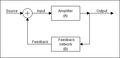
The figure above displays the block diagram for a feedback amplifier. The gain may be calculated with either voltage or current. The current and voltage designators for the block diagram are as follows: source (is and vs), input (ii and vi), feedback (if and vf), and output (io and vo). The open loop voltage gain and the open loop current gain are defined as:
Av = vo / vs
Ai = io / is
The system voltage gain and system current gain are defined as:
Avf = Av / (1+Av*B)
Aif = Ai / (1+Ai*B)
where B is the feedback transfer ratio. The quantity A*B is the loop gain. A positive loop gain implies that the feedback is negative. A negative loop gain would mean that the feedback is positive which may lead to oscillations in the circuit. The loop gain is also equivalent to the following:
Gv = vf / vi
Gi = if / ii
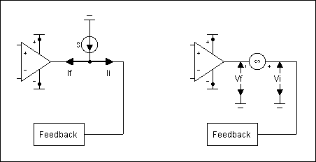
Now it is not necessary to break the loop in order to measure these gains. The loop may be opened in its feedback path and the appropriate test signal injected. Injecting a current into the signal path will split the current into its feedback and input currents. This ratio can then be measured to produce a current loop gain. The voltage gain may also be measured through the same technique by placing a voltage source in the loop. The gain measurement setups are displayed in the figure below.
|
|
For the actual measurements, macros will be created for the voltage and current injections in order to measure the voltages and currents with user functions. Both the voltage loop gain and the current loop gain must be taken into account to measure the total loop gain. They are related through the following equation:
G + 1 = (Gv + 1) || (Gi + 1)
where
x || y = (x * y)/(x + y)
The above equation may be reduced to:
G = (Gi * Gv - 1)/(Gi + Gv + 2)
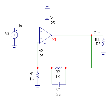
As is normal in parallel calculations, the lower of the current or voltage gain will be the one that dominates. The feedback amplifier circuit that is to be analyzed is shown below. The circuit is shown in its closed loop measurement configuration.
|
|
Macros
Two macros need to be created for open loop measurement. These macros will inject the test signal and provide the means for measuring the loop gain. One macro will measure the open loop current gain and the other will measure the open loop voltage gain.
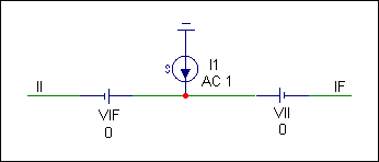
The figure below displays the GI macro which will measure the open loop current gain. The macro consists of two batteries and the independent SPICE current source called I. The current source is defined as 'AC 1' so that it will provide a 1A small signal current in the AC analysis. The two batteries are used to measure the current in each direction. They are given a voltage of 0 so that they don't affect simulation results. The VII battery measures the Ii current and the VIF battery measures the If current.
|
|
The figure below displays the GV macro which will measure the open loop voltage gain. The macro consists of two batteries and the independent SPICE voltage source called V. The voltage source is defined as 'AC 1' so that it will provide a 1V small signal voltage in the AC analysis. The two batteries provide fixed nodes (VIM and VFM) within the macro. This is done so that the user functions may reference a fixed node in its equation because the input and output pins of the macro always change to what they are connected to which would make a global .define more complex. The batteries are again given a voltage of 0 to not affect the simulation.
|

|
User Functions
The user functions provide a means for users to create their own functions and operators by being able to pass parameters through a .define statement. The three user functions created for loop gain are shown below.
.define GIM(X) I(X.VIF)/I(X.VII)
.define GVM(X) V(X.VFM)/(-V(X.VIM))
.define G(X1,X2) (GIM(X1)*GVM(X2)-1)/(GIM(X1)+GVM(X2)+2)
GIM(X) defines the equation for the loop current gain. The parameter it passes is the PART attribute of the GI macro in the schematic. It divides the current in the VIF battery by the current in the VII battery. Both of these batteries exist inside the GI macro. GVM(X) defines the equation for the loop voltage gain. The parameter it passes is the PART attribute of the GV macro in the schematic. It divides the voltage of the VFM node by the negative voltage of the VIM node. Both of these nodes exist within the GV macro. G(X1,X2) defines the equation for the total open loop gain. It passes two parameters. X1 is the PART attribute for the GI macro in the schematic and X2 is the PART attribute for the GV macro in the schematic.
The user functions within a circuit are local to that one circuit. However, the user functions in the DEF.MC5 file are globally available to all circuits. This file is accessed from the User Definitions item on the Options menu.
Analysis Example
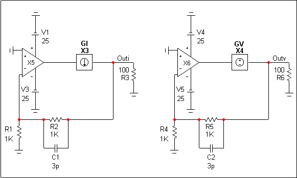
The schematic that is to be analyzed is shown below. This is actually two copies of the circuit from the closed loop circuit above. The AC source has been removed from the noninverting inputs and the GI and GV macros have been added to the feedback loops. The circuit on the left measures the open loop current gain and the circuit on the right measures the open loop voltage gain. The opamp that is being analyzed is the OP_27. The circuits need to be analyzed at the same time in order to produce the total gain as the total gain relies on both the open loop current gain and the open loop voltage gain.
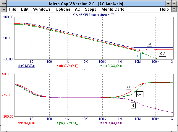
The open loop analysis is shown below. The top plot contains the open loop magnitude responses for the current gain (GI), the voltage gain (GV), and the total gain (G). The bottom plot contains the open loop phase responses for the current gain (GI), the voltage gain (GV), and the total gain (G). Note that the user functions have been used to plot these curves. The PART attribute for the GI macro in the schematic is X3, and the PART attribute for the GV macro in the schematic is X4.
Because the loop has never been broken, the operating point calculations are exactly the same between the closed loop circuit and the open loop circuits.
|
|
|
|
|
|
|


