|
|
 |
Measuring Input Impedance
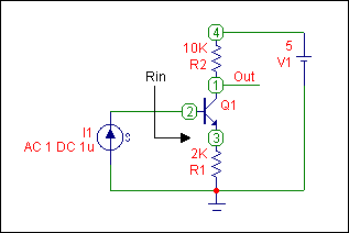
In Micro-Cap, there must be an AC source present in the schematic to run a meaningful AC analysis. This means that the circuit must contain one of the following: sine source, pulse source, user source, or the V or I SPICE independent sources. To measure input impedance, the I SPICE independent source will be used. This source is found in the Waveform Sources section of the Analog Primitives and is called 'I'. The current source is placed across the nodes where the impedance is to be measured. The figure below displays a test schematic that will measure the input impedance of a transistor circuit.
|

|
In this circuit, the current source is placed between ground and the base of the transistor. Rin marks the impedance that the source is looking into. The VALUE attribute of the current source has been defined as:
AC 1 DC 1u
This provides a DC bias of 1 microamp during the operating point calculation and a one amp small signal current during the AC analysis. The AC current is defined as one so that the impedance will be equivalent to the voltage across the current source. This is calculated from the equation:
V = I * Z
where if I is equal to 1, then:
V = Z
The input impedance of the circuit is the reflected impedance of the emitter multiplied by the beta of the transistor. It can be approximately represented by the following equation:
Rin = (Beta + 1) * Remitter
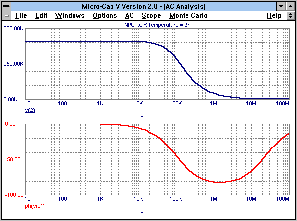
The value computed from this equation for the input impedance is 402 kohms. The AC analysis results for this circuit are displayed in the figure below.
|

|
Since the impedance is equivalent to the voltage across the source, the waveform V(2) has been chosen to plot the magnitude of the impedance. 2 is the node number at the base. The actual value of the impedance calculated in MC5 is 404.9 kohms which compares favorably with the calculated value of 402 kohms. The second plot is the phase of the impedance, and this waveform is plotted through the expression ph(V(2)).
|
|
|
|
|


