|
|
 |
Stepper Motor Model
Here is a new model for Micro-Cap, the DC stepper motor. It is based on a model created by Dave
Wilson, currently at TI. For more information, see http://e2e.ti.com/support/applications/motor_
drivers/f/38/t/283566.aspx.
This model handles detent torque and back EMF. It does not consider eddy current losses. To accurately
simulate eddy current losses would require at least a rudimentary finite element analysis of the
motor structure.
This model does not consider such nonlinearlities. It is a linear, parametric model
that produces reasonably faithful results. Note that the model internalizes a constant viscous friction
load and a physical angular stop.
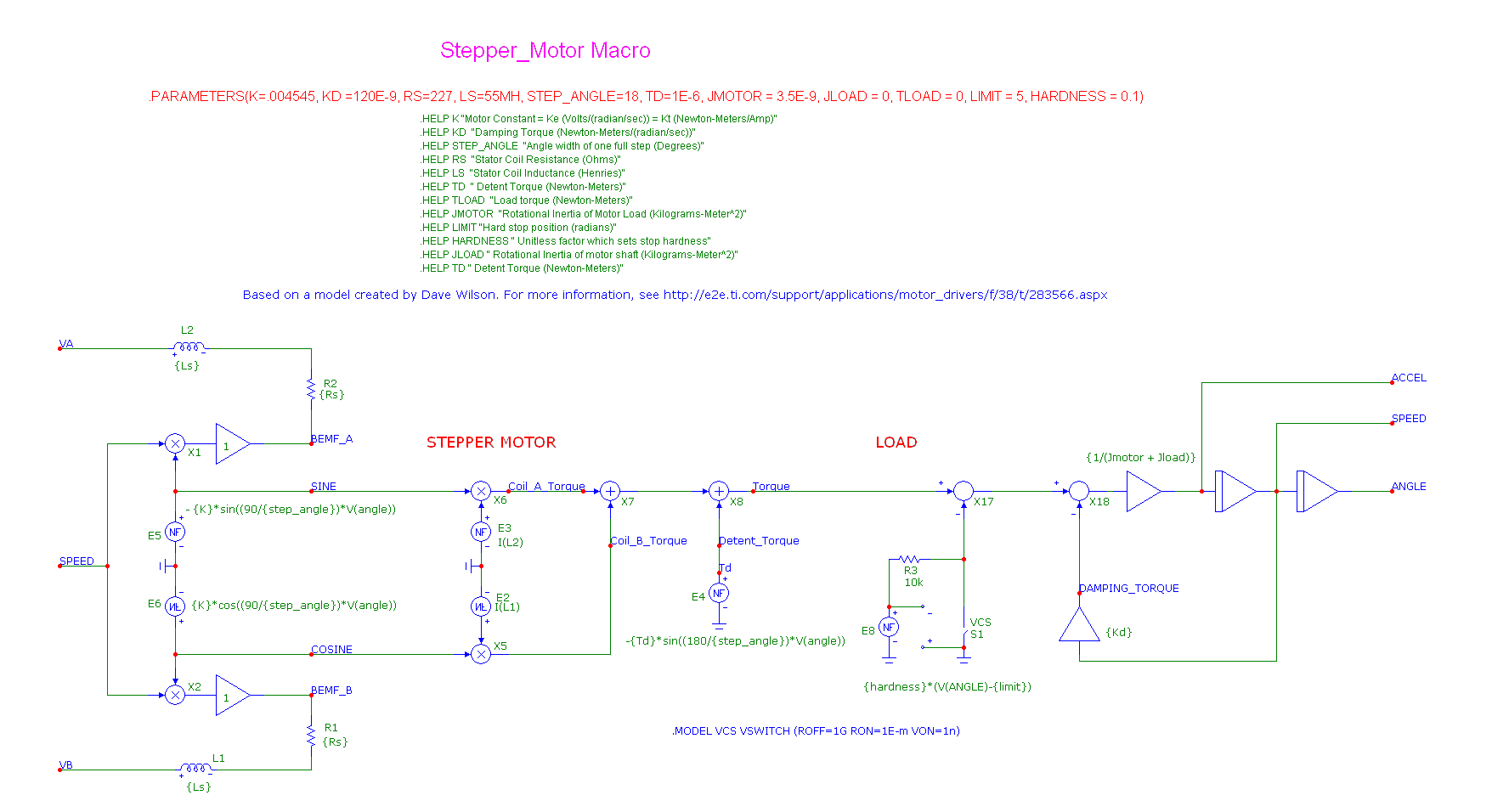
Here is what the model looks like:
|

|
The model includes these parameters:
K Motor Constant = Ke (Volts/(radian/sec)) = Kt (Newton-Meters/Amp)
KD Damping Torque (Newton-Meters/(radian/sec))
STEP_ANGLE Angle width of one full step (Degrees)
RS Stator Coil Resistance (Ohms)
LS Stator Coil Inductance (Henries)
TD Detent Torque (Newton-Meters)
TLOAD Load torque (Newton-Meters)
JMOTOR Rotational Inertia of Motor Load (Kilograms-Meter^2)
LIMIT Hard stop position (radians)
HARDNESS Unitless factor which sets stop hardness
JLOAD Rotational Inertia of motor shaft (Kilograms-Meter^2)
TD Detent Torque (Newton-Meters)
How does it work? Well you can drive a stepper motor in a variety of ways. Here is one way using
non-overlapping pulses.
|
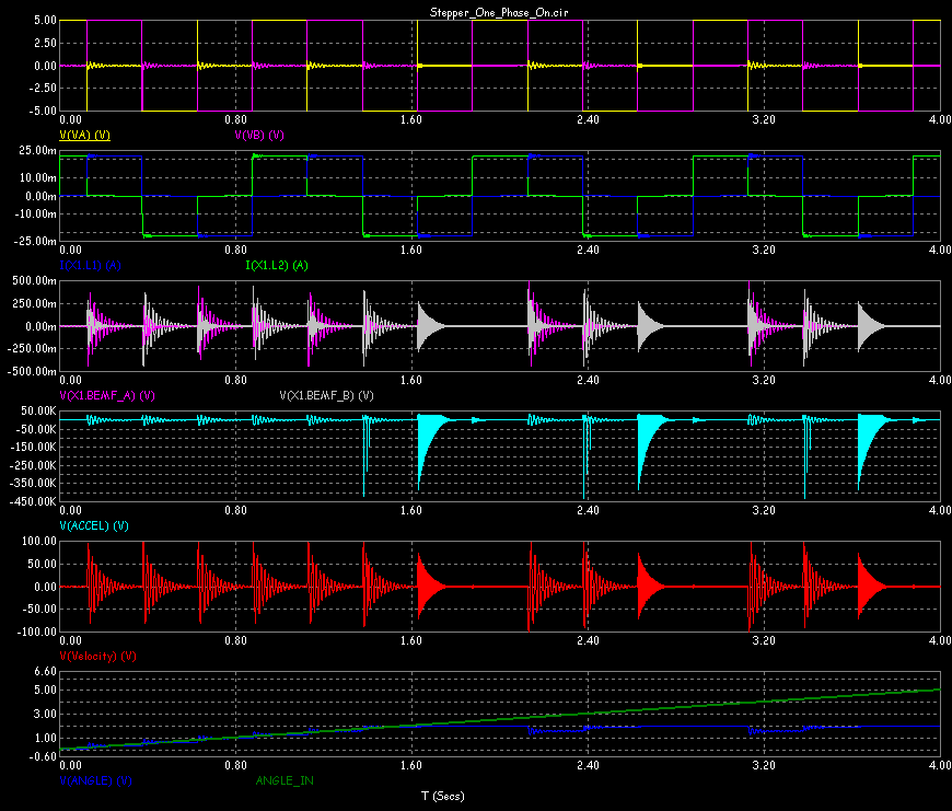
Here is what the waveforms look like.
|

|
Here we've plotted the voltage at VA and VB, which consist of two non-overlapping pulses. Next
we've plotted the armature currents flowing from the generators. Since the current values are not
brought out to pins, you must plot them by referring to the motor's name (X1) like this:
I(X1.L1)
I(X1.L2)
where X1 is the proper name for the motor macro. In your circuit it may be different.
Similarly, we've plotted the back emf of the A and B coils this way:
V(X1.BEMF_A)
V(X1.BEMF_B)
The last three plots show the acceleration (radians/sec/sec), the velocity (in radians/sec), and finally
the angle (in radians). The angle increases until it hits the LIMIT parameter value, which in this case
is 2 radians.
Note that the model has two input pins, one for each phase. It has four outputs: Torque, Velocity,
Angle, and Accel (Acceleration). The outputs have been labelled with grid text to make it easy to
identify the plots.
Here is another way to drive the motor, using overlapping phases.
Here is its transient analysis.
Here we've plotted the voltage at VA and VB, which consist of two overlapping pulses. Next we've
plotted the armature currents flowing from the generators. As in the last circuit, the current values
are not brought out to pins, so we must plot them by referring to the motor like this:
I(X1.L1)
I(X1.L2)
Similarly, we've plotted the back emf of the A and B coils this way:
V(X1.BEMF_A)
V(X1.BEMF_B)
The last four plots show the acceleration (radians/sec/sec), the velocity (in radians/sec), the angle
(in radians) and the Torque (in Newton-meters). The angle increases until it hits the LIMIT parameter
value, which in this case is 3 radians.
One of the most efficient ways to drive a stepper motor is called micro-stepping. The next figure
shows a micro-stepped motor.
Here is its transient analysis. Note the stepped sine drive waveforms generated by the sine wave
NFV sources, the ZOH macros, and the VCS switches.
|
|
|
|
|


