|
|
 |
AC Induction Motor Model
Here is a new AC induction motor model for Micro-Cap. It is based on a model created by Sohor
and Kubov. For more information, see http://valvolodin.narod.ru/articles/Induction3phMotor1.
pdf. The signs of BX and BY have been reversed from those in the article.
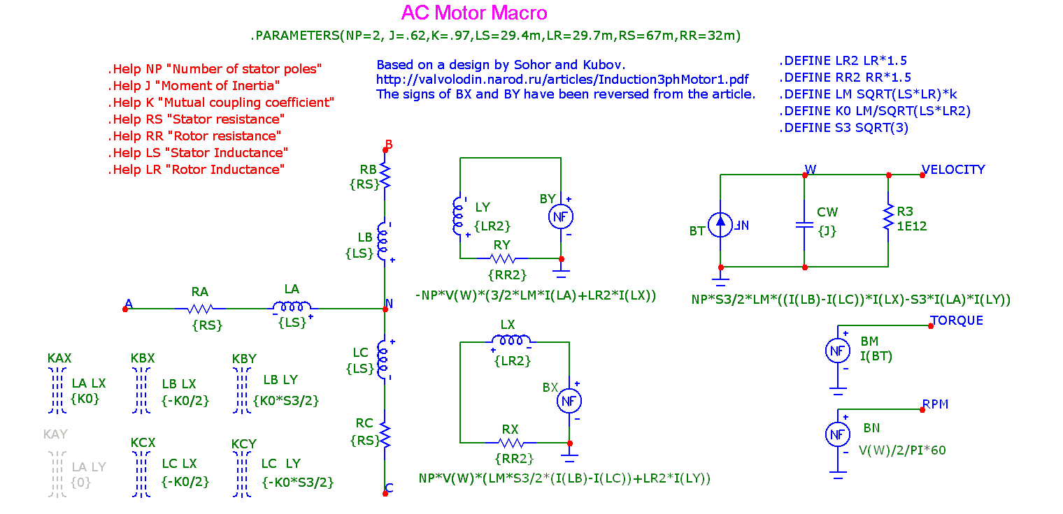
Here is what the motor model looks like:
|

|
The model provides three pins for the input AC drive: A, B, and C. It provides three pins for output:
Velocity, Torque, and RPM. The load is attached separately between the Velocity node and ground.
Three types of load are provided: no load, viscous friction, and square law friction. Each of these
load types may be attached to the Velocity pin to see how the motor responds. The model currently
has no provision for eddy current losses.
The next figure shows a typical test setup.
The next figure shows the motor armature current, torque, and RPM waveforms for the Torque0
(no load) condition.
Here are the response waveforms for the Torque1 (viscous friction) and Torque2 (square
law friction) load conditions.
|
|
|
|
|


