|
|
 |
Displaying Calculations in Dynamic DC
The Dynamic DC analysis calculates the DC operating point for the circuit and dynamically
displays the resulting DC node voltage, device current, and device power values on the schematic.
The current and power displays are only available for the analog primitive devices such as the
diode or the NPN. Any components that are modeled as a subcircuit or macro will not have currents
and powers available for display. Some users may want to expand on the available set of displayed
values by using formula text to create their own calculations. With formula text, the existing
voltage, current, and power values may be referenced to create new calculations such as device
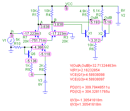
voltages, differential voltages, and subcircuit power calculations. The schematic below displays
the use of formula text in making additional voltage, current, and power calculations for the circuit.
|

|
The circuit is a simple differential amplifier. Formula text has been entered below the circuit.
There are two varieties of schematic grid text that can use formulas. The first form is as follows:
=formula
Grid text of this form behaves like a small spreadsheet. The presence of the = at the first character
position tells Micro-Cap that the following text should be calculated as a formula. The four voltage
calculations use this form, and the expressions used for them are shown as follows.
=V(OutA,OutB)
=V(R1)
=VCE(Q1)
=VCE(Q3)
Note that each of these expressions must be added separately through the Grid Text mode as this type of
formula text can only handle a single expression. The first expression calculates the differential voltage
between nodes OutA and OutB. The second expression calculates the voltage across the R1 resistor. The last
two expressions calculate the voltages between the collector and emitter leads for the Q1 and Q3 NPN
transistors.
The second form of formula text is as follows:
text...[formula]...text
Formula text of this type is calculated only if the Formula checkbox is enabled in the Text dialog box.
The advantage to this form as opposed to the first one is that any number of formulas may be entered within
the same text object. The power and current calculations in the schematic have been specified in this form.
The following text was used for these calculations:
PD(X1) = [V(OutA,9)*I(R5)]
PD(X2) = [V(OutB,9)*I(R2)]
I(V3)=[I(V3)]
I(V3)=[V(R8)/R(R8)+V(R9)/R(R9)]
Since the X1 and X2 NPN transistors are actually modeled as a subcircuit, the basic power displays in Dynamic
DC are not available for them. A simple calculation of the power is used instead where the voltage from the
collector to the emitter is multiplied by the current through the resistor that is in series with the collector
lead. The current calculations produce the same calculation using two different methods. The first I(V3) just
calculates the current through the V3 source whereas the second calculation uses the voltage and resistance
values of the two resistive branches that connect to the V3 source. As can be seen in the result, Kirchoff's
laws are met.
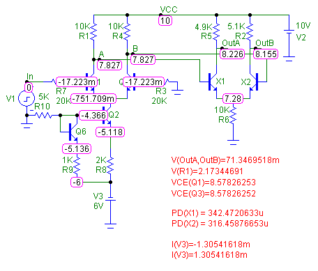
One nice feature of the formula text is that the calculations are updated when the circuit is modified. The
schematic below shows the updated calculations when the V2 source has been increased to 10V.
|

|
|
|
|
|


