|
|
 |
Constant Power Load Macro
In some simulations, it can be useful to have a load that draws a constant power in the
circuit. Applications that use a load such as this can be found when simulating mains,
SMPS, DC/DC converters, or other power circuits. To model a constant power load, the
simplest method is to use the nonlinear function current source (NFI). The obvious
equation to define the NFI with would be similar to the following:
I = Power/V(I)
where I is the current produced by the source, Power is the specified constant power,
and V(I) is the voltage across the current source. While this equation would work fine
in certain configurations, it can often cause convergence issues should the voltage
across the current source become small since an excessively large current would be
generated. The solution is to adapt the above equation so that when the applied voltage
across the load becomes too small, the impedance that the current source represents
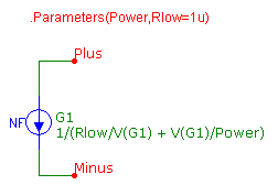
clips at a minimum value. The macro circuit below shows one technique for modeling
the constant power load.
|

|
The macro circuit has two parameters that are passed through to it: Power and Rlow. The
Power parameter defines the constant power value in Watts that the load will draw. The
Rlow parameter specifies the minimum resistance that the load will clip at should the
voltage across the load become too small.
The macro circuit consists of just a single NFI source. The VALUE attribute of the
source has been defined as:
1/(Rlow/V(G1) + V(G1)/Power)
where V(G1) represents the voltage across the current source. At voltages near zero,
the equation reduces to:
I = V(G1)/Rlow
so that the current source represents an impedance with a value of Rlow. At larger
voltages, the equation reduces to:
I = Power/V(G1)
which is the basic constant power equation. In this case, the current out of the source
will be adjusted depending on the voltage across the load so that a constant power is
generated.
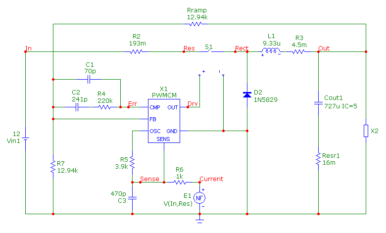
The circuit below shows the use of the constant power load macro. The circuit is a
current mode buck converter that was derived by Christophe Basso. The constant power
load macro is the X2 device at the Out node. The parameters for the macro were defined
as:
POWER=50
RLOW=10u
The load will generate a constant 50W in its normal operating range and will clip at
10uohms when the voltage across the load becomes too small.
|

|
The transient analysis of this schematic is displayed below. The simulation has been
run for 250us. Two waveforms have been plotted.
The top waveform displays the voltage at node Out. After the initial transient, the
output voltage settles down into the 5V range.
The bottom waveform displays the power dissipated at the load. The expression used to
plot the power at the load is:
V(Out)*I(X2.G1)
The X2.G1 entry refers to the G1 current source within the X2 macro which is the
constant power load macro. As expected, the waveform shows that a constant 50W was
dissipated throughout the simulation.
|
References
1) "Modeling Constant Power Loads", Microsim Tutorial Including Application Notes and
Design Ideas, Microsim, 1995.
2) "Switch-Mode Power Supplies: SPICE Simulations and Practical Designs", Christophe
Basso, McGraw Hill, 2008.
|
|
|
|
|


