|
|
 |
Simulating the Lorenz Attractor
The Lorenz attractor describes how the state of a nonlinear, three dimensional, dynamic system
changes over time in a chaotic fashion. The attractor was originally discovered by Ed Lorenz
who derived it from a simplified model of convection rolls in the earth's atmosphere. However,
it also arises within lasers and dynamos.
The three differential equations that define the Lorenz attractor are:
dx/dt = Sigma*(y-x)
dy/dt = (Rho-z)*x - y
dz/dt = x*y - Beta*z
where Sigma is often referred to as the Prandtl number, Rho is often referred to as the
Rayleigh number, and Beta is a geometric factor.
In Micro-Cap, differential equations such as these can be simulated by using the behavioral
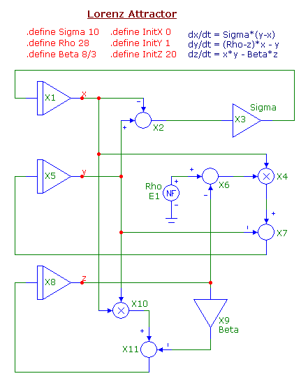
models available in the Macro section of the Analog Primitives. The schematic for the Lorenz
attractor appears below.
|

|
The nodes x, y, and z calculate voltages equivalent to their corresponding variables in the above
equations. The x variable is calculated using an Int macro, a Sub macro, and an Amp macro. The
Sub macro (X2) subtracts the voltage at node y by the voltage at node x. The difference is then
fed into an Amp macro (X3) whose Gain parameter is set to Sigma. The output of the Amp macro is
then input into an Int macro (X1) which calculates the integral to produce x.
The y variable is calculated using an Int macro, two Sub macros, a Mul macro, and an NFV function
source. The NFV function source (E1) produces a voltage equivalent to Rho. The Sub macro (X6)
subtracts the Rho value by the voltage at node z. The difference is then fed into a Mul macro
(X4) where it is multiplied by the voltage at node x. This product is then fed into another Sub
macro (X7) where it is subtracted by the voltage at node y. This difference is then input into
an Int macro (X5) which calculates the integral to produce y.
The z variable is calculated using an Int macro, a Mul macro, an Amp macro, and a Sub macro. The
voltages at nodes x and y are multiplied together using the Mul macro (X10). The voltage at node
z is scaled by the factor Beta using the Amp macro (X9). These two products are input into a Sub
macro (X11). The difference is then input into the Int macro (X8) which calculates the integral
to produce z.
The values of Sigma, Rho, and Beta are set through define statements. The following three define
statements are also present in the schematic:
.define InitX 0
.define InitY 1
.define InitZ 20
These three define statements set the initial values for the x, y, and z variables. The InitX,
InitY, and InitZ are used to define the VINIT parameter for the X1, X5, and X8 Int macros
respectively. The VINIT parameter of the Int macro sets an initial voltage at the output of the
integrator. As with other chaotic systems, the Lorenz attractor is very sensitive to these initial
conditions. Even a small change in these will produce an entirely different plot.
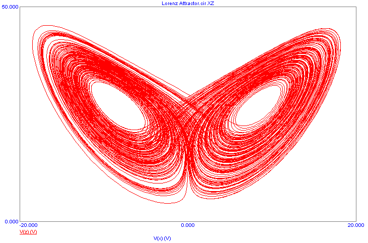
The common settings to show chaotic behavior with the Lorenz attractor is to set Sigma to
10, Rho to 28, and Beta to 8/3. A 200 second transient analysis is run using these values which
produces the classic butterfly plot when V(Z) is plotted versus V(X) as shown below.
|

|
|
|
|
|


